Wavetronix Click 200 (surge suppression) (CLK-200) - Quick-reference Guide User Manual
Click 200 lightning surge, Installer quick-reference guide, Wire power and communication
Click 200 Lightning Surge
INSTALLER QUICK-REFERENCE GUIDE
www.wavetronix.com
801.734.7200
2
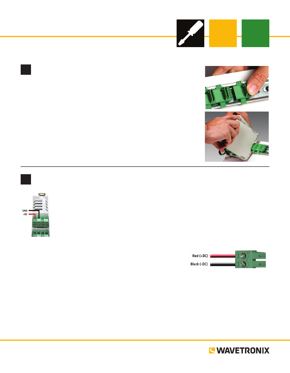
Wire power and communication
The Click 200 can take power and communications in through its screw terminals and send
it through any T-bus it is mounted on. To wire power through the Click 200: wire +DC from
the power supply into the screw terminal marked +DC on the PROTECTED side of the
Click 200. Wire -DC from the power supply into the screw terminal marked -DC.
Alternatively, power can be wired from the power supply into a 5-screw terminal block,
which can then be plugged into the left side of the T-bus. To wire power through the 5-screw
terminal block: wire +DC from the power supply into
the screw terminal marked +DC on the 5-screw terminal block. Wire
-DC from the power supply into the screw terminal marked -DC.
The front of the Click 200 has two communication ports (communica-
tion through the device’s screw terminals will be covered in Part 4).
˽
RJ-45 jack – A convenient way to connect RS-485 communications to a rack card
˽
DB-9 connector – Connect between here and your computer to configure your sensor
Note. Unlike on other Click devices, the RS-232 lines are not connected to the RS-485 lines on the Click
200. Be sure to test both lines as part of your installation process.
1
Mount the device
The Click 200 mounts over a T-bus for power and communication:
1 If the Click 200 was shipped with the T-bus connector attached, remove
the connector from the module.
2 Snap the connector onto the DIN rail by positioning it over the rail with
the male connector pointing to the right. Hook one arm over the edge of
the DIN rail and press down on the other arm until it snaps into place.
3 Connect the T-bus connector to the rest of the T-bus by sliding them
together until you hear them snap into place.
4 Mount the Click 200 onto the DIN rail: position it properly over the T-
bus connector, hook the lip over the lower edge of the DIN rail, and use a
rocking motion to snap the module into place.