Redundant ring, v-mode configuration, Prepare the fibre optical network – Westermo ODW-720-F2 User Manual
Page 16
16
6651-2235
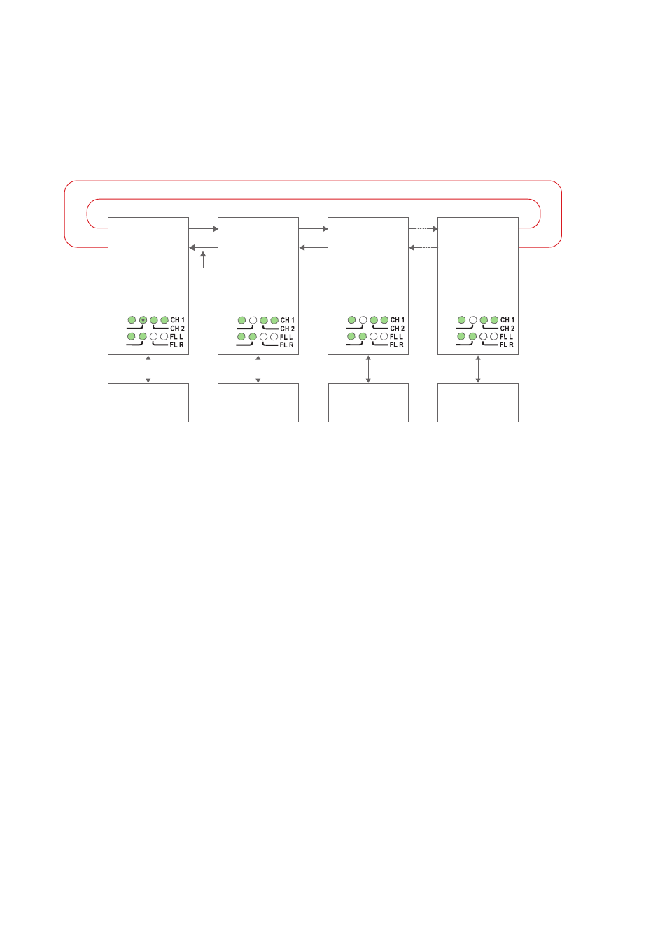
Redundant ring, V-mode configuration
In a redundant ring an extra fibre pair is used. This extra fibre pair is used to carry data
if one of the other fibre pairs breaks. In V-mode mode an ODW-720 network will behave
as a 4-wire bus. Where the first ODW-720 (leftmost in the picture below) will able to
communicate in full duplex with any other unit, but other units are incapable of commu-
nicating with each other.
RX2
TX2
Focal point
S1:8 ON
S2:2 ON
S2:3 ON
Ring member
S1:8 ON
S2:2 ON
S2:3 OFF
Ring member
S1:8 ON
S2:2 ON
S2:3 OFF
Ring member
S1:8 ON
S2:2 ON
S2:3 OFF
Device 1
Communicates
with all other devices
Device 2
Communicates
with device 1 only
Redundant fibre pair. Not used under normal operation.
Device 3
Communicates
with device 1 only
Device n
Communicates
with device 1 only
TX1
RX1
RX2
TX2
TX1
RX1
RX2
TX2
RS-232
RS-232
RS-232
Fibre
pair
Fibre
pair
Fibre
pair
Fibre
pair
used
to
carry
data
FP LED
is on to
indicate
focal point
RS-232
TX1
RX1
RX2
TX2
TX1
RX1
PWR
FP
TD
RD
PWR
FP
TD
RD
PWR
FP
TD
RD
PWR
FP
TD
RD
Prepare the fibre optical network
• Configure all ODW-720 units for the correct speed and data format using DIP-
switches S1:1 – S1:7.
• Set DIP-switch S1:8 in the ON position (V-mode) on all ODW-720 units.
• Set DIP-switch S2:2 in the ON position (redundant ring) on all ODW-720 units.
• One, and only one, of the ODW-720 units must be configured as a Ring Focal Point by
setting DIP-switch S2:3 to the ON position. (The Ring Focal Point acts as a logical end
point in the optical fibre ring, thus forming a bus type of structure)
• Set DIP-switch S2:1 and S2:6 as desired. See page 29 “RTS to CTS transport” and
page 33 “Status port” for more information.
• Verify that DIP-switches S2:4, S2:5 and S2:8 are set in the OFF position.
• Connect the fibre pairs between the units. Always connect CH 1 from one unit to
CH 2 on the next unit as shown in the picture above.
• Connect the power supply to all units and verify that all fibre links become active.
(CH 1 and CH 2 LED’s are on, FL L and FL R LED’s are off).
• Connect the communication devices to the corresponding ODW-720 unit.
• The network is now up and running.
Note: In an ODW-720 fibre optic network there will be some additional processing
delays that do not exist in an electrical bus. It is possible that the application must be
adjusted to accommodate these delays if using many ODW-720 units in a large network.
See page 31 “Calculating system processing delay” for more information on how to
determine the overall system delay time.