Westermo ODW-720-F2 User Manual
Page 17
17
6651-2235
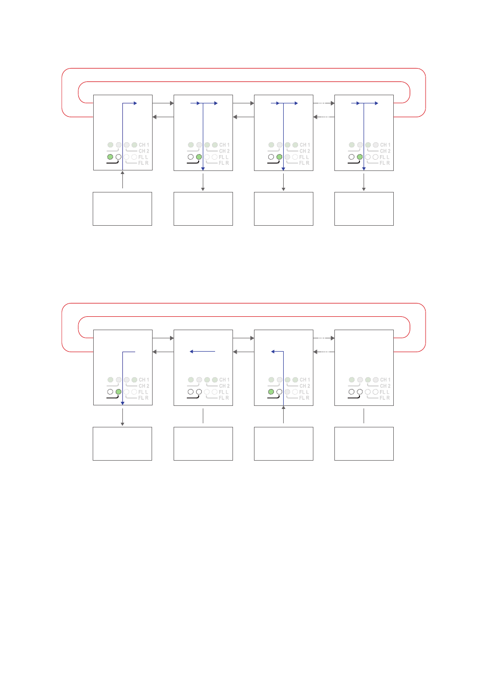
Data transport in redundant ring, V-mode configuration
RX2
TX2
Device 1
Sending
Device 2
Receiving
Device 3
Receiving
Device n
Receiving
TX1
RX1
RX2
TX2
TX1
RX1
RX2
TX2
RS-232
RS-232
RS-232
Fibre
pair
Fibre
pair
Fibre
pair
Focal point
RS-232
TX1
RX1
RX2
TX2
TX1
RX1
PWR
FP
TD
RD
PWR
FP
TD
RD
PWR
FP
TD
RD
PWR
FP
TD
RD
Data from comminication device 1 is received at the ODW-720 RS-232 port (as indi-
cated by the TD LED), data bits are retimed according to the preset rate and sent out
on the optical fibre TX1. The next ODW-720 unit receives data at optical fibre RX2
(as indicated by the RD LED), and data is sent out on the RS-232 port. Data is also
repeated out on TX1 on to the next ODW-720 unit.
RX2
TX2
Device 1
Receiving
Device 2
Not sending or
receiving any data
Device 3
Sending
Device n
Not sending or
receiving any data
TX1
RX1
RX2
TX2
TX1
RX1
RX2
TX2
RS-232
RS-232
RS-232
Fibre
pair
Fibre
pair
Fibre
pair
Focal point
RS-232
TX1
RX1
RX2
TX2
TX1
RX1
PWR
FP
TD
RD
PWR
FP
TD
RD
PWR
FP
TD
RD
PWR
FP
TD
RD
Data from some other communication device, for example device 3, is processed in the
same way and sent out on optical fibre TX2. Intermediate ODW-720 units will receive
this data at optical fibre RX1 and repeat it out on optical fibre TX2. But, intermedi-
ate units will not send any data received at RX1 on to the RS-232 port. Only the first
ODW-720 (leftmost in the picture above) will have incomming data from optical fibre
RX1 sent out on the RS-232 port.
I.e. the first ODW-720 is able to communicate in full duplex with any other unit, but
other units are incable of communicating with each other.
Notice that the Ring Focal Point never repeats incoming data.