Redundant ring, dual channel, v-mode configuration, Prepare the fibre optical network – Westermo ODW-720-F2 User Manual
Page 24
24
6651-2235
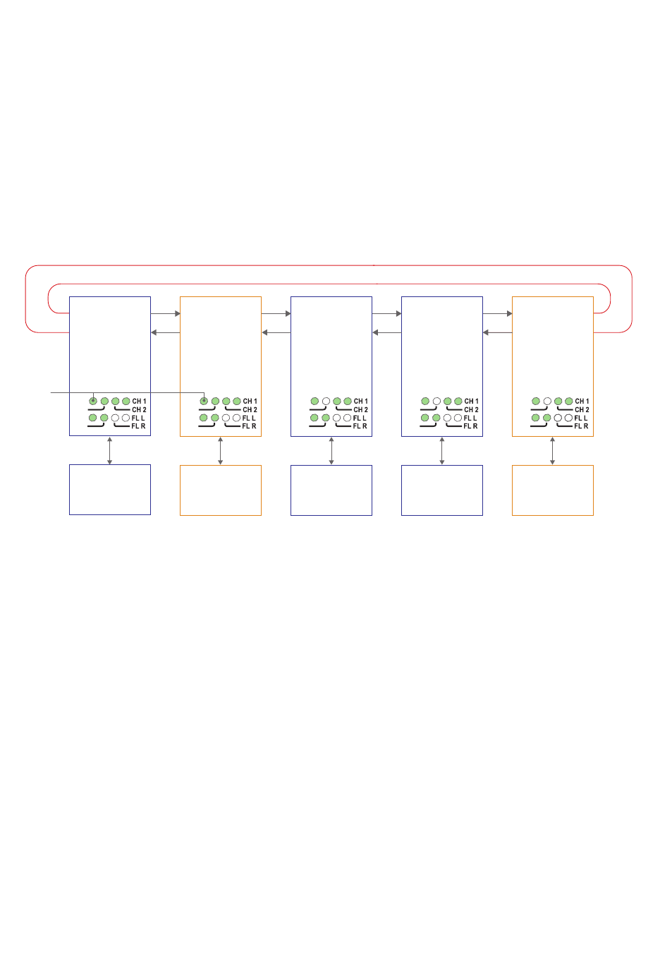
Redundant ring, dual channel, V-mode configuration
In a redundant ring an extra fibre pair is used. This extra fibre pair is used to carry data if
one of the other fibre pairs breaks.
In dual channel mode it is possible to use two separate data streams in a single ODW-
720 network. However, all ODW-720’s must be set to the same speed and data
format. This, of course, limits the number of possible applications for a dual channel
network.
In V-mode mode an ODW-720 network will behave as a 4-wire bus. Where the first
ODW-720 (leftmost in the picture below) will able to communicate in full duplex with
any other unit, but other units are incapable of communicating with each other.
Prepare the fibre optical network
• Configure all ODW-720 units for the correct speed and data format using DIP-
switches S1:1 – S1:7. Again, notice that all ODW-720’s must be set to the same speed
and data format.
• Set DIP-switch S1:8 in the ON position (V-mode) on all ODW-720 units.
• Set DIP-switch S2:2 in the ON position (redundant ring) on all ODW-720 units.
• Set DIP-switch S2:5 in the ON position (dual channel system) on all ODW-720 units.
• All ODW-720 units that are to use the primary data channel (“blue” units in the
picture above) must have DIP-switch S2:4 set to the OFF position. Units that are to
use the secondary data channel (“orange” units in the picture above) must have DIP-
switch S2:4 set to the ON position.
• One of the primary data channel and one of the secondary data channel ODW-720
units must be configured as a Ring Focal Point by setting DIP-switch S2:3 to the ON
position.
• Set DIP-switch S2:6 as desired. See page 33 “Status port” for more information.
• Verify that DIP-switches S2:1 and S2:8 are set in the OFF position.
Redundant fibre pair. Not used under normal operation.
RX2
TX2
Device 1
Communicates with
device 3 on the
primary data channel
Device 2
Communicates with
device 4 on the
secondary data channel
Device 3
Communicates with
device 1 on the
primary data channel
Device 5
Communicates with
device 2 on the
secondary data channel
TX1
RX1
RX2
TX2
TX1
RX1
RX2
TX2
RS-232
RS-232
RS-232
Fibre
pair
Fibre
pair
Fibre
pair
RS-232
TX1
RX1
RX2
TX2
TX1
RX1
PWR
FP
TD
RD
PWR
FP
TD
RD
PWR
FP
TD
RD
Device 4
Communicates with
device 1 on the
primary data channel
RS-232
Fibre
pair
RX2
TX2
TX1
RX1
PWR
FP
TD
RD
PWR
FP
TD
RD
FP LED
is on to
indicate
focal point
Primary channel
Focal point
S1: 8 ON
S2: 2 ON
S2: 3 ON
S2: 4 OFF
S2: 5 ON
Secondary channel
Focal point
S1: 8 ON
S2: 2 ON
S2: 3 ON
S2: 4 ON
S2: 5 ON
Primary channel
Ring member
S1: 8 ON
S2: 2 ON
S2: 3 OFF
S2: 4 OFF
S2: 5 ON
Primary channel
Ring member
S1: 8 ON
S2: 2 ON
S2: 3 OFF
S2: 4 OFF
S2: 5 ON
Primary channel
Ring member
S1: 8 ON
S2: 2 ON
S2: 3 OFF
S2: 4 ON
S2: 5 ON