Led indication during optical link failure, Rts to cts transport – Westermo ODW-720-F2 User Manual
Page 29
29
6651-2235
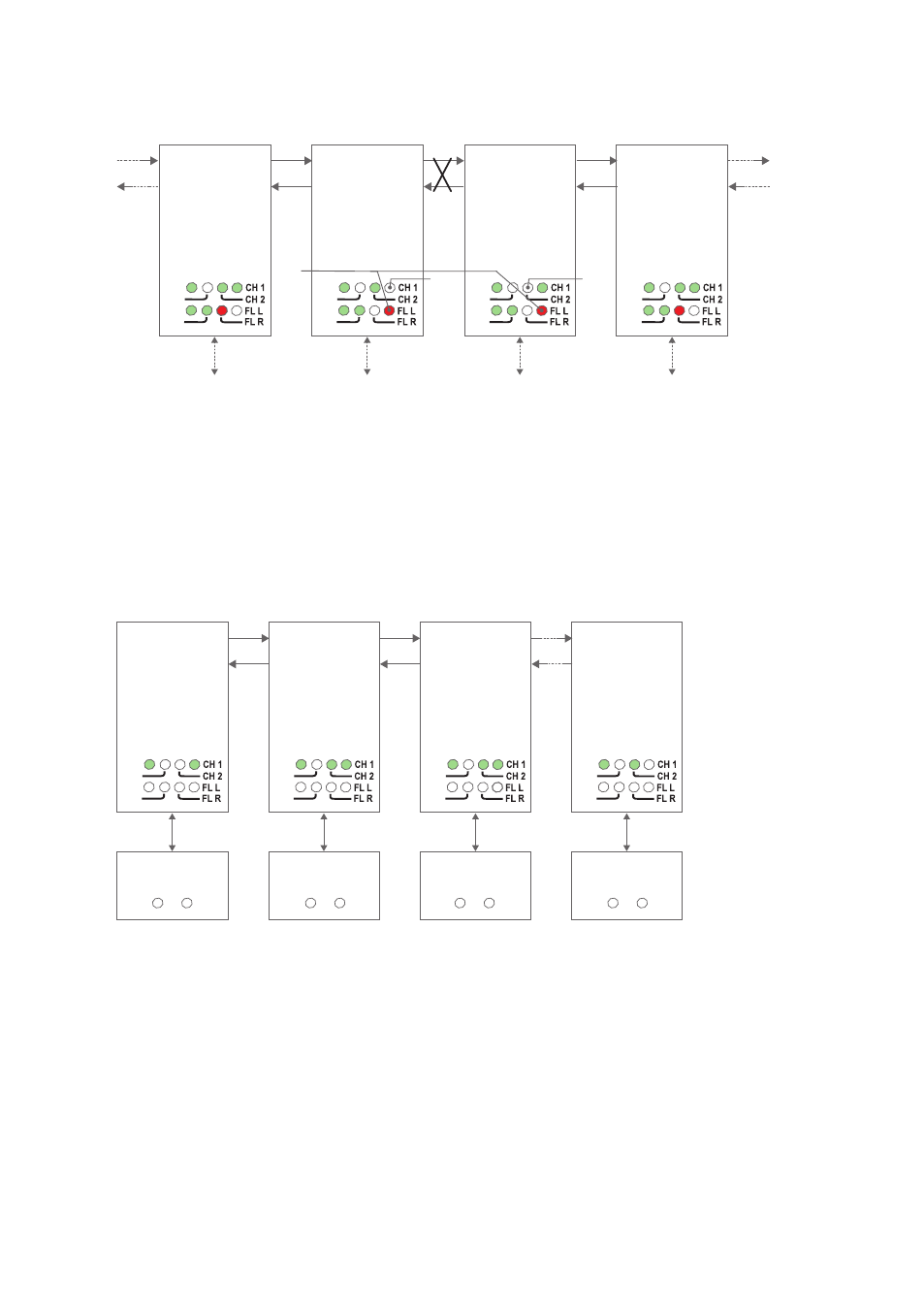
LED indication during optical link failure
RX2
TX2
TX1
RX1
RS-232
PWR
FP
TD
RD
RX2
TX2
TX1
RX1
RS-232
PWR
FP
TD
RD
RX2
TX2
TX1
RX1
RS-232
PWR
FP
TD
RD
RX2
TX2
TX1
RX1
RS-232
PWR
FP
TD
RD
Fibre
pair
Fibre
pair
Fibre
pair
FL L
LED
is on
CH 1
LED
is off
CH 2
LED
is off
Faulty
segment
If an optical fibre segment fails, to determine wich fibre segment has failed, look at the
FL L, FL R, CH 1 and CH 2 LED’s as show in the picture above.
RTS to CTS transport
When setting DIP-switch S2:1 to the ON position the RS-232 RTS signal input
can be used to assert the RS-232 CTS signal output on other units.
RX2
TX2
Device 1
TX1
RX1
RS-232
PWR
FP
RTS CTS
RTS CTS
RTS CTS
RTS CTS
TD
RD
RX2
TX2
Device 2
TX1
RX1
RS-232
PWR
FP
TD
RD
RX2
TX2
Device 3
TX1
RX1
RS-232
PWR
FP
TD
RD
RX2
TX2
Device n
TX1
RX1
RS-232
PWR
FP
TD
RD
S2: 1 ON
S2: 1 ON
S2: 1 ON
S2: 1 ON
Fibre
pair
Fibre
pair
Fibre
pair
If no device asserts the RTS input, the CTS output to all other devices will also
be unasserted.