Location of interface ports and led’s, Ethernet connection tx (4 ports) – Westermo Lynx-x08-F2G-S2 User Manual
Page 10
Advertising
10
6643-2220
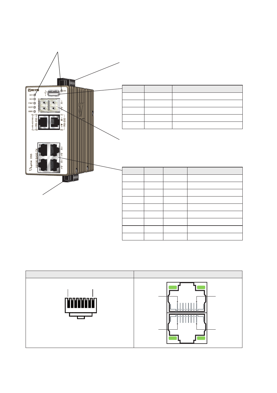
Location of interface ports and LED’s
LED Indicators (for details see page 14)
Power connection (for details see page 7 and 13)
SFP transceivers (for details see page 9)
I/O connection
(for details see page 9 and 13)
USB
Position
Direction
Description
No. 1
Out
VBUS
No. 2
In/Out
D–
No. 3
In/Out
D+
No. 4
Out
GND
Shield
In/Out
Connected to protective earth
Ethernet connection TX (4 ports)
Position
Signal Direction Description
No.1
TD+
In/Out
Transmitted/Received data
No. 2
TD–
In/Out
Transmitted/Received data
No. 3
RD+
In/Out
Transmitted/Received data
No. 4
–
Not Connected
No. 5
–
Not Connected
No. 6
RD–
In/Out
Transmitted/Received data
No. 7
–
Not Connected
No. 8
–
Not Connected
Shield
Connected to PE
RJ-45 connector (Front view)
Male
Female
Pin 8
Pin 1
Pin 1
Pin 8
Pin 8
Pin 1
Advertising