Westermo TD-23 User Manual
Page 14
14
6600-2204
Leased Line
Pos.
Direction*
Description
Product
marking
No. 1
Out
4-wire Transmit
TX
In/Out
2-/4-wire
Receive/ Transmit
No. 2
Out
4-wire Transmit
In/Out
2-/4-wire
Receive/ Transmit
No. 3
In
4-wire Receive
RX
No. 4
In
4-wire Receive
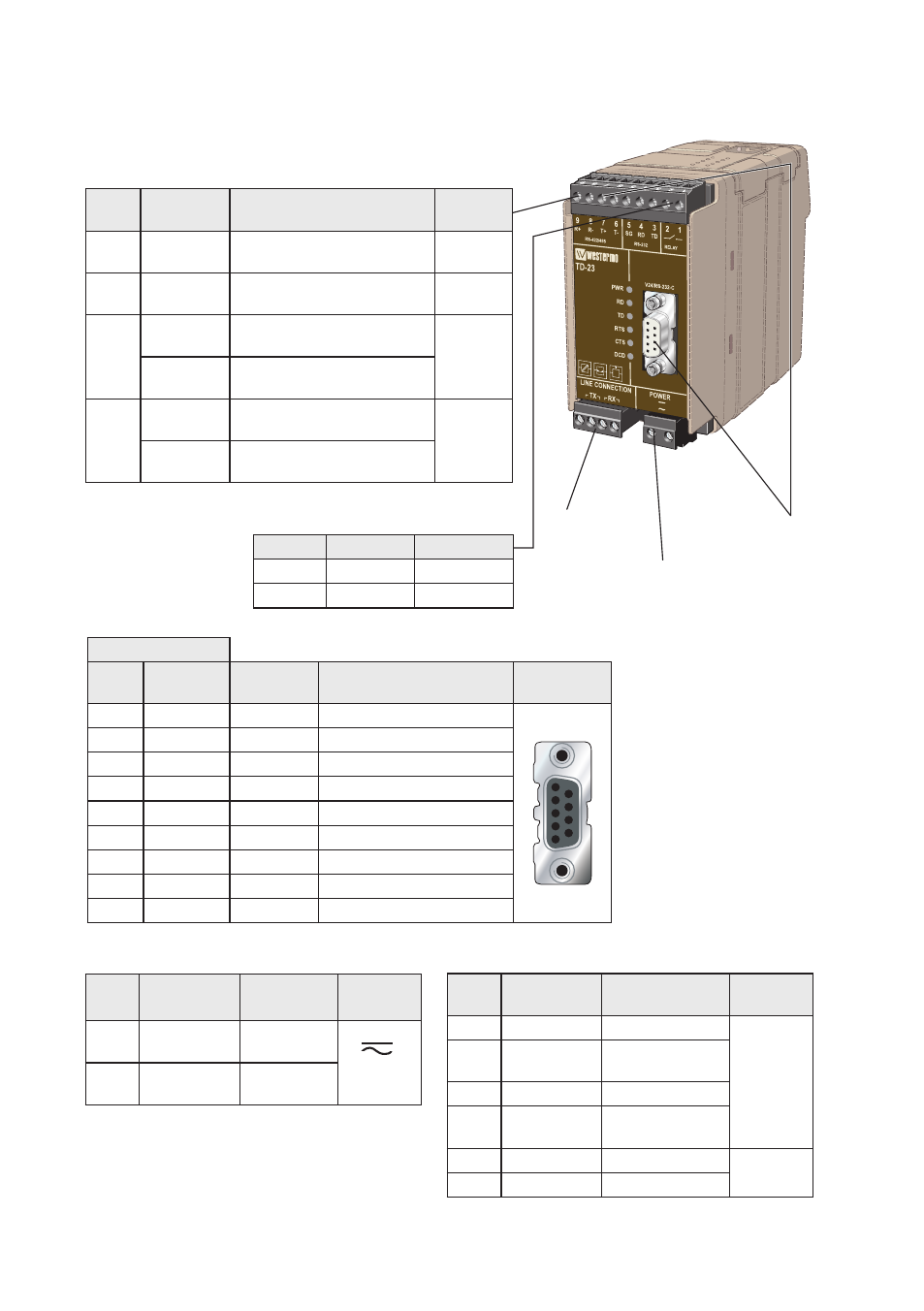
Location of Interface ports, LED’s and DIP-switches
TD-23 LV
* Direction relative this unit. NC = Not Connected
RS-422/485
9-pos. Direction* Description
Product
marking
No 9
In
R+ (A’) Receive
RS-422/485 4-wire
R+
No 8
In
R– (B’) Receive
RS-422/485 4-wire
R–
No 7
Out
T+ (A) Transmit
RS-422/485 4-wire
T+
In/Out
T+/R+ (A/A’) Transmit/Receive
RS-422/485 2-wire
No 6
Out
T– (B) Transmit
RS-422/485 4-wire
T–
In/Out
T–/R– (B/B’) Transmit/Receive
RS-422/485 2-wire
Relay (optional)
Position Direction* Description
No. 1
Out
Normal open
No. 2
Out
Common
RS-232 (DTE)
Position
D-sub
Screw
terminal
Direction* Description
D-sub
description
No. 1
Out
Data Carrier Detect (DCD)
1
2
3
4
5
6
7
8
9
No. 2
No. 4
Out
Received Data (RD)
No. 3
No. 3
In
Transmitted Data (TD)
No. 4
NC
Data Terminal Ready (DTR)
No. 5
No. 5
–
Signal Ground (SG)
No. 6
Out
Data Set Ready (DSR)
No. 7
In
Request To Send (RTS)
No. 8
Out
Clear To Send (CTS)
No. 9
NC
Ring Indicator (RI)
RS-232 (DTE)
Fore details, se below
Power connection LV
Fore details, se below
Leased Line
Fore details,
se below
Power connection LV
Pos.
Direction*
Description
Product
marking
No. 1
In
AC: Neutral
DC: –Voltage
No. 2
In
AC: Line
DC: +Voltage