S1 dip-switch 2 or 4 wire line side – Westermo TD-23 User Manual
Page 17
17
6600-2204
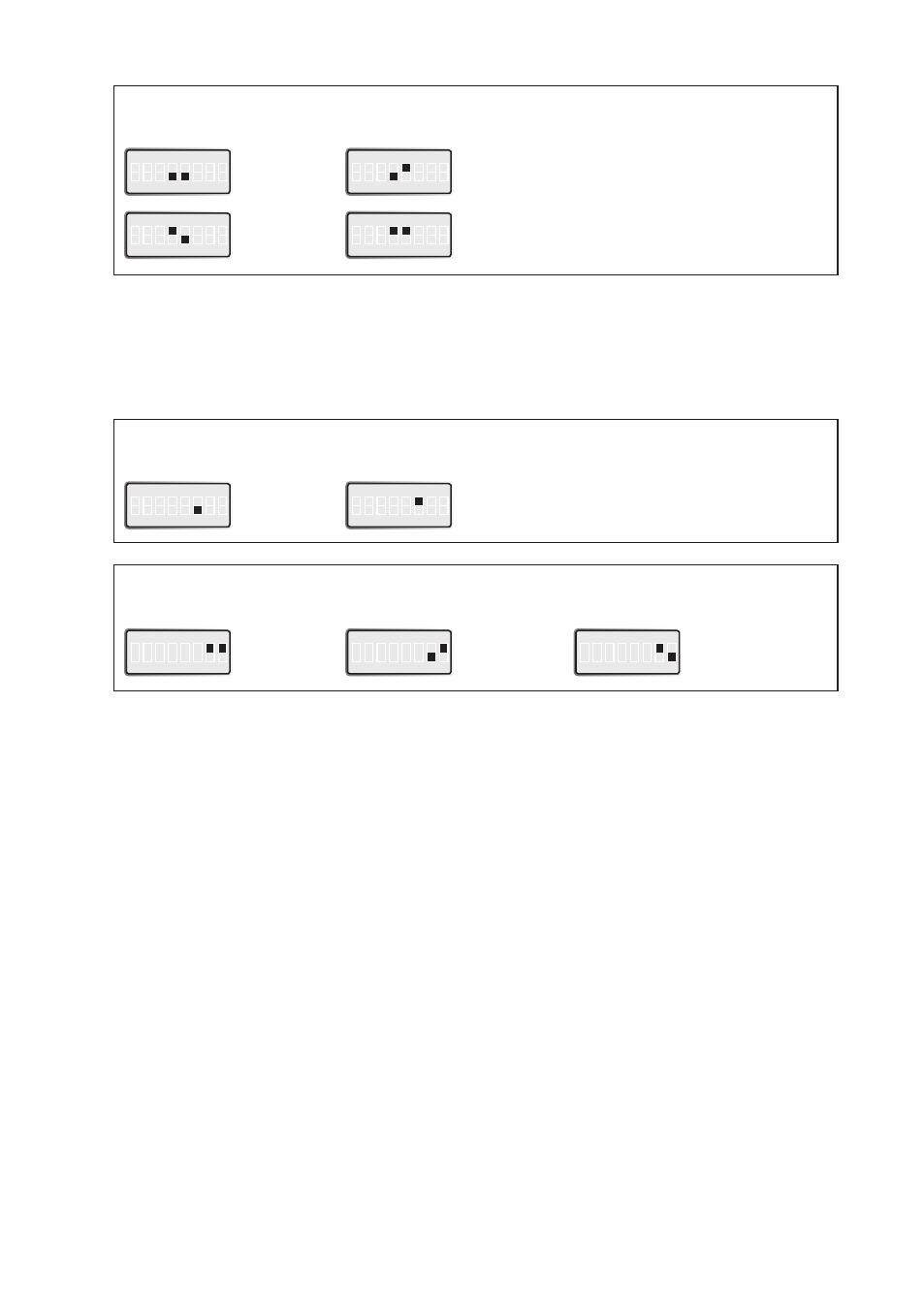
S1 DIP-switch
Carrier active using RTS or incoming data
ON
1 2 3 4 5 6 7 8
Incoming data
ON
1 2 3 4 5 6 7 8
Permanent carrier
ON
1 2 3 4 5 6 7 8
RTS
S1 DIP-switch
Selection of minimum level detection DCD
ON
1 2 3 4 5 6 7 8
–45 dBm
ON
1 2 3 4 5 6 7 8
–33 dBm
ON
1 2 3 4 5 6 7 8
–27 dBm
ON
1 2 3 4 5 6 7 8
–23 dBm
S1 DIP-switch
2 or 4 Wire Line side
ON
1 2 3 4 5 6 7 8
4-wire
ON
1 2 3 4 5 6 7 8
2-wire
Selection of minimum level, DCD detection specifies the minimum power level the receiver can handle. With the
receiver having a dynamic range of 30 dBm, this means that with the level set to –15 dBm the TD-23 will pick up
signals in the range –15 dBm to –45 dBm. We recommend that you try your network with the factory settings.
If disturbances are detected (faulty characters or other errors) decrease the level step by step. If there is no
communication because of a weak signal the receiver sensitivity can be increased step by step until satisfactory
transmission quality is achieved.
If the DTE uses the control signal- (RTS) the RTS signal is used to activate the transmitter. If the DTE does not
control RTS or if RS-485 is used then the transmitter is activated by incoming data. In this case the data is buffered
in the TD-23 while the carrier is established. By setting RTS always active a permanent carrier will be established.
This is the typical setting for a full duplex 4-wire communication.