Connections, Power interface cord, Pin-out interface – Westermo DR-270 User Manual
Page 12: Rs-232 interface (dce female), Ethernet tx connections (rj-45 connector) lan 0–3
12
6622-2241 • 29000589, REV.A
WWAN
PRIMARY
WIFI
SECONDARY
WWAN
SECONDARY
WIFI
PRIMARY
9-36VDC, 3,5A
MAIN
AUX.
SERIAL 0
LAN3
LAN2
LAN1
LAN0
DSL
DR-270
DSL Router
POWER
NET
SIM
DAT
SIM 1
SIM 2
3G/GPRS
WIFI
DSL
0
1
2
3
LAN
SIGNAL
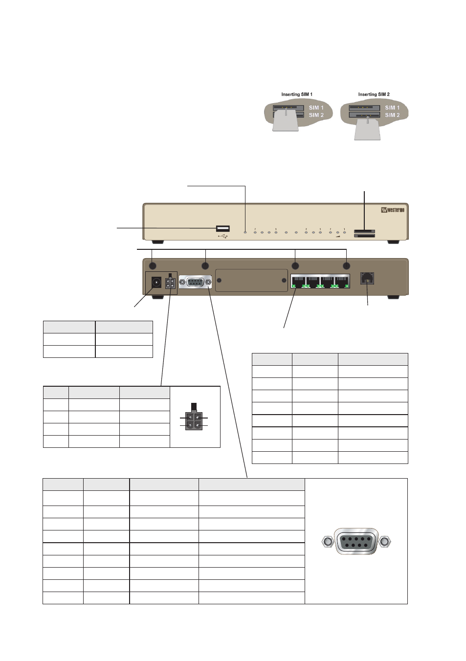
SIM Card Sockets
The two sockets at the left side of the front panel are for the GSM SIM card(s)
that you will receive from your service providers. SIM 1 and SIM 2
cannot be used to access two networks simultaneously.
The SIM card(s) should be inserted into SIM cardholders on the
right of the front panel as illustrated below.
In both cases, the end of the SIM card with the chamfered corner
should be inserted first. For SIM 1 the contacts should be face
down. For SIM 2 the contacts should be face up.
Antenna interface (optional)
Connections
Power interface cord
Cable
Description
Black
– VDC
Red
+ VDC
Pin-out interface
Pin
Wire Color
Signal
2
3
4
1
1
Black
Gnd
2
Blue
Input
3
Green
Input/Output
4
Red
Power
DSL interface
USB Host Connector
SIM card sockets
LED Indicators
(for details
see next page)
RS-232 interface (DCE Female)
Position
Name
Direction
Description
5
1
6
9
1
DCD
Out
Data Carrier Detect
2
RxD
Out
Receive Data
3
TxD
In
Transmit Data
4
DTR
In
Data Terminal Ready
5
SG
–
Signal Ground
6
DSR
Out
Data Set Ready
7
RTS
IN
Request to Send
8
CTS
Out
Clear to Send
9
RI
Out
Ring Indicator
Ethernet TX Connections
(RJ-45 connector) LAN 0–3
Position
Direction
Description
1
In/Out
TD+
2
In/Out
TD–
3
In/Out
RD+
4
–
Not Connected
5
–
Not Connected
6
In/Out
RD–
7
–
Not Connected
8
–
Not Connected