Westermo DR-270 User Manual
Page 14
Advertising
14
6622-2241 • 29000589, REV.A
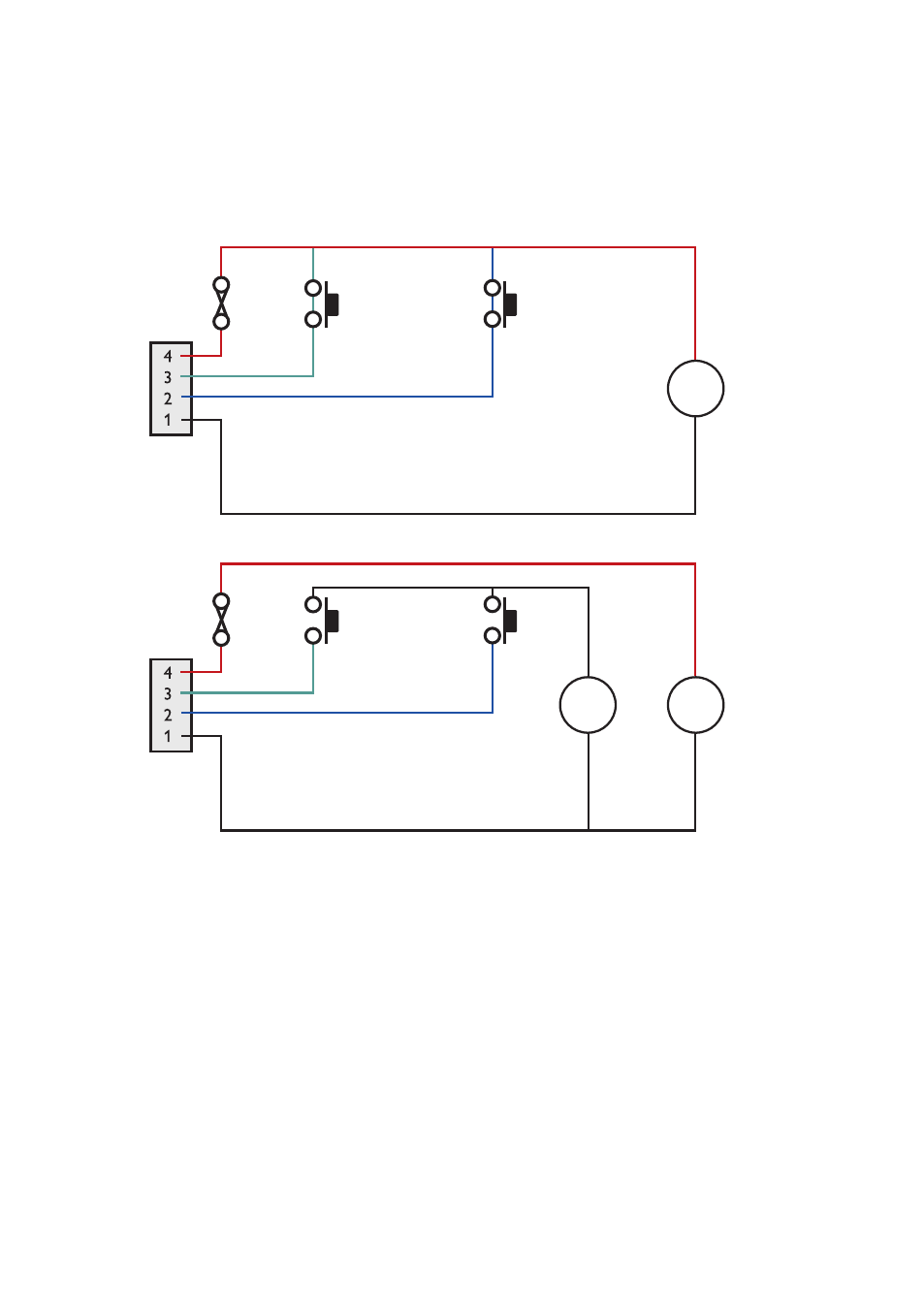
Description of AUX-connector and I/O signal lines
The auxiliary power connector has two programmable signal lines. One is an input line,
the other can be configured as either an input line or an output line. The mode of opera-
tion of the input/output line is configurable through the CLI.
The signal lines can be wired as shown in the following diagrams
POWER
11 – 28 V
Switch
Switch
INPUT/OUTPUT
INPUT
GND
+
–
POWER
Switch
Switch
INPUT/OUTPUT
INPUT
GND
11 – 28 V
+
–
4 – 28 V
+
–
2 Inputs, Supply Voltages up to 28 VDC
2 Inputs, Supply Voltages up to 58 VDC
Advertising
This manual is related to the following products: