5 full wire speed, 6 twisted pair port specification, 1 introduction – Westermo U200 Operator manal User Manual
Page 10: 2 mdi/mdi-x
V4.5
www.westermo.com
U/R/T200 series
- 10 -
switch engine will drop packets. Packet re-transmission is then required and must be handled
by the end nodes (e.g. TCP).
A MAC table of 8 K entries and a packet memory of 1Mbyte is adequate for large networks.
4.5 Full Wire Speed
The Switch supports full wire speed. This equates to 100Mbit/s full duplex on every port.
100Mbit/s in each direction on all ports equals 200Mbit/s per port.
4.6 Twisted Pair Port Specification
4.6.1 Introduction
The T/R/U200 series is available with up to eight copper ports. The copper ports support the
long cable specification that enables standard CAT5e copper cables to run up to 150 Meters
when used with devices that also support this specification. This highlights the enhanced
design specification the switch employs
when used in noisy electrical environments. In
industrial networks long cables should be avoided but equipment specified according to long
cable specification gives more margins for disturbances.
Port configuration is available via the IP configuration tool or the push buttons on the front
panel of the Switch. See the Installation Guide for details.
4.6.2 MDI/MDI-X
There are two types of copper Ethernet ports available; MDI (Medium Dependant Interface)
and MDIX (Medium Dependant Interface Crossover). The MDI port types are associated with
copper interfaces available on NICs (Network Interface Cards), PLCs, VSDs and DCSs etc.
The latter type of interface (MDI-X) is found on Hubs or Switches.
In addition there are two types of Ethernet cable available. These are referred to as a ‘straight
through cable’ or ‘crossed cable’.
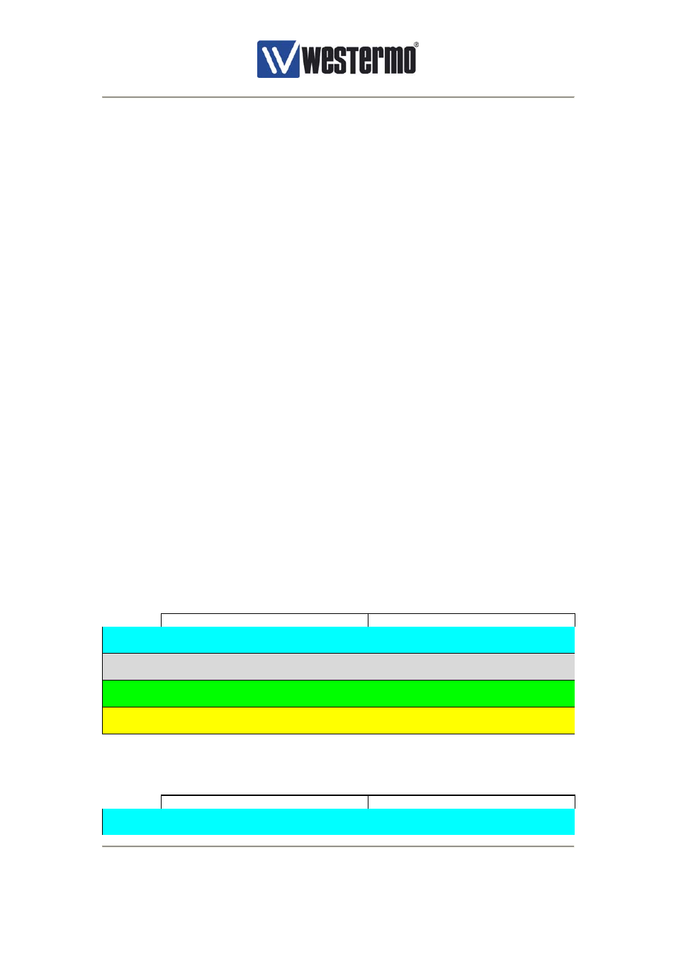
4.6.3 Straight Connection –Switch-PLC, Hub-PLC, Switch-NIC etc.
Connector A
Connector B
Pair 1
pin
4
<------->
Pin
4
pin
5
<------->
Pin
5
Pair 2
RD +
pin
3
<------->
Pin
3
RD +
RD -
pin
6
<------->
Pin
6
RD -
Pair 3
TD +
pin
1
<------->
Pin
1
TD +
TD -
pin
2
<------->
Pin
2
TD -
Pair 4
pin
7
<------->
Pin
7
pin
8
<------->
Pin
8
4.6.4 Crossed Connection – Switch-Switch, Hub-Hub, Switch-Hub
Connector A
Connector B
Pair 1
pin
4
<------->
Pin
7
pin
5
<------->
Pin
8