3 power supply & fault contact connection diagram – Westermo U200 Operator manal User Manual
Page 14
V4.5
www.westermo.com
U/R/T200 series
- 14 -
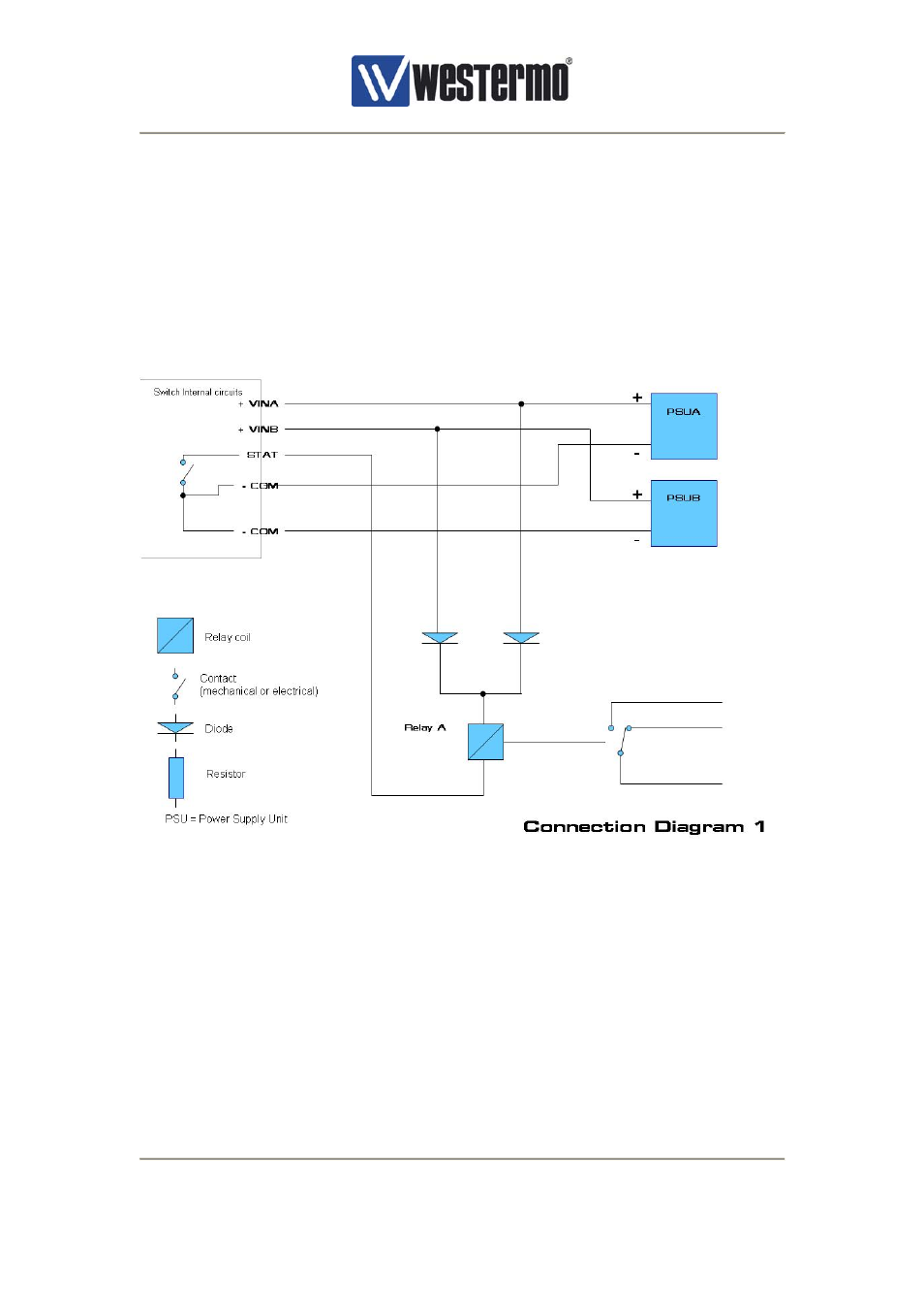
5.3 Power Supply & Fault Contact Connection Diagram
Power supply connection terminals +VinA and +VinB are not interconnected internally within
the Switch. -COM terminals on the other hand are internally connected to each other. –COM,
+Vin and STAT terminals have an isolation barrier to internal logic and chassis ground that
withstand 1500Vrms.
In some cases polarity needs to be reversed or current increased on the fault contact, in such
cases an external relay may be used. Dual relays may be used if monitoring of individual
power supplies is required. Two example circuit diagrams are presented as a guideline, see
Figure 5 and Figure 6.
Figure 5, Power and fault contact – connection diagram 1
The diodes can be omitted if only one power supply is used. The diode can be any general
purpose diode capable of carrying the current through the relay winding. The function of the
circuit is that the current through the relay winding goes from the positive terminal of the
power supply via diodes and into the STAT connection. The STAT pin is normally connected
to the –COM terminal during normal operation resulting in a magnetised relay in normal
mode. The STAT pin will float when an error occurs and the relay will be de-energised.