Westermo U200 Operator manal User Manual
Page 15
V4.5
www.westermo.com
U/R/T200 series
- 15 -
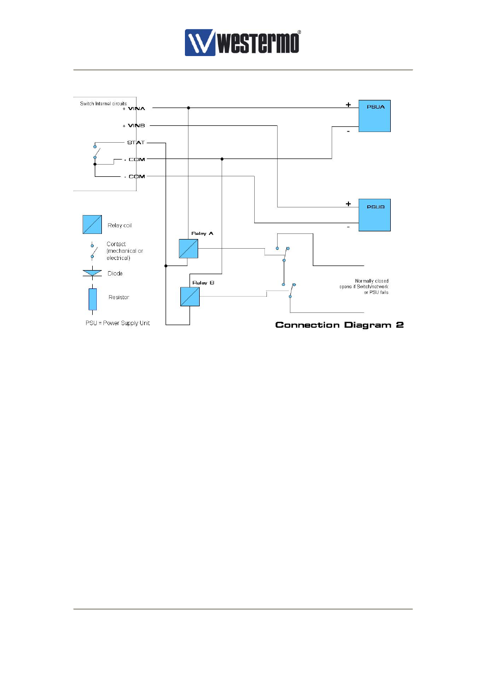
Figure 6, Power and fault contact – connection diagram 2
Example circuit 1, see Figure 5, will not indicate if one of the external power supplies fails,
while example circuit 2 will if this is required, see Figure 6. The only difference between the
two examples (except that two relays are used) is that each relay is powered from only one of
the power supplies. The result of this is that if a power supply is failing the corresponding
relay will be de-energised.
Example circuit 3, see Figure 7 shows how to connect the fault contact (status connection) to
a PLC. The reason for connecting the fault contact to a local PLC can be that the PLC needs
to know the status of the network in order to decide operational mode or to summarize alarms
if SNMP and SNMP traps are not used, see chapter 9. Connection of status output of the two
PSUs can be done in the same way. The fault contact in the switch is an electronic relay with
an internal resistance of approx. 8Ω. When calculating the pullup resistor R the threshold
voltage of the digital input on the PLC needs to be taken into account. Also the maximum
power dissipated in the resistor R as well as the maximum current thru the fault contact. If
+24V supply is used to pullup the resistor (+5V may also be used) as in connection diagram
3, a suitable resistor is 2,2kΩ 0,5W.