3 x.21/v.35 dce to x.2, 2 g.703 to g.703 transpa, X.21/v.35 dce to x.21/v.35 dce – ATL Telecom AM200 User Manual
Page 30: G.703 to g.703 transparent timing
ATL User Guide
AM200 Modem
30
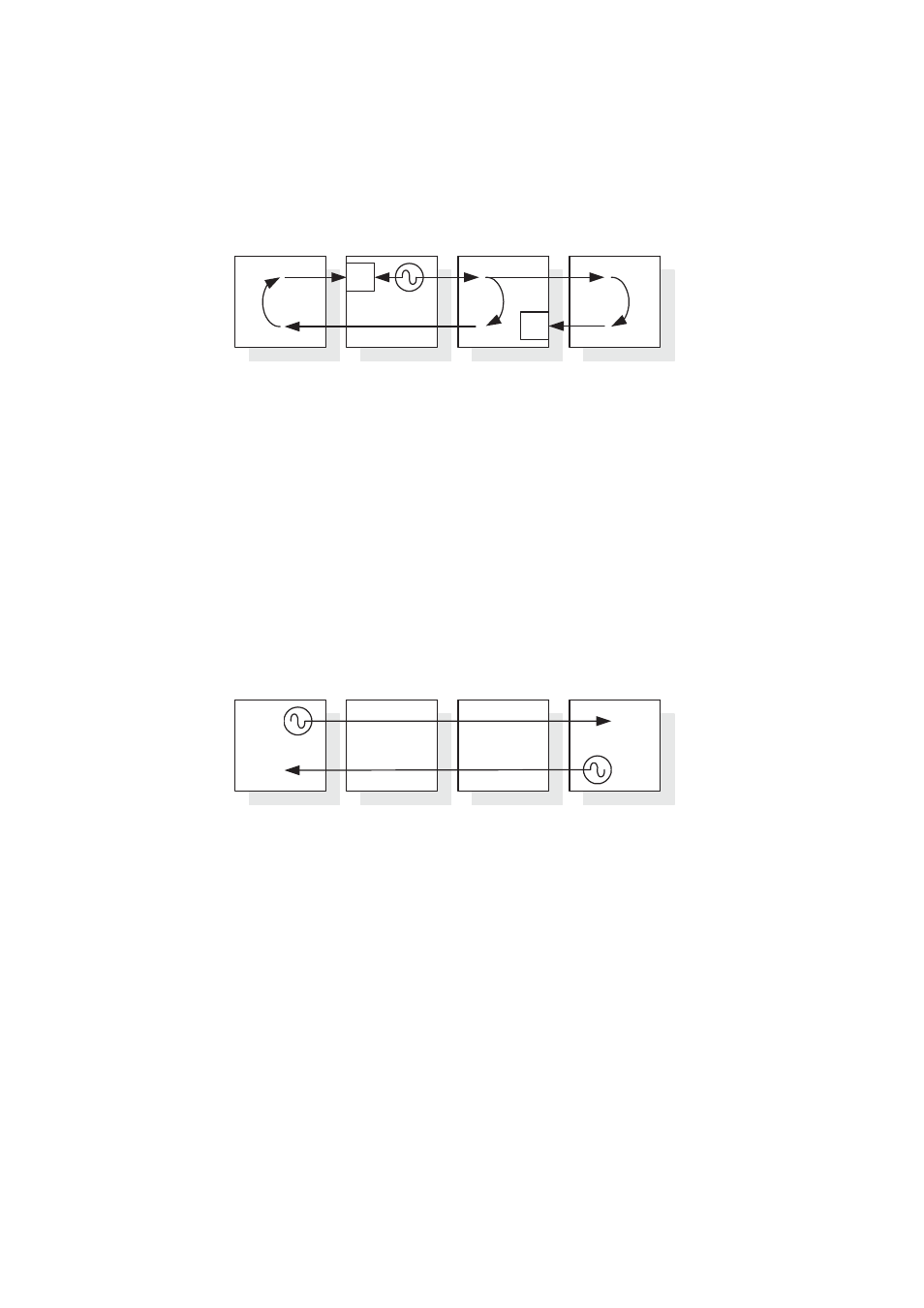
7.1.1.3 X.21/V.35 DCE to X.21/V.35 DCE
The terminals connected to the digital section at both ends are DTEs. A clock inside the CO then becomes the
reference clock for the entire system.
1.
At the CO, select the 'DCE' timing option for the Nx64 port.
2.
At the CPE, select the 'DCE' mode option for the Nx64 port.
This is the default timing mode for Nx64.
7.1.2 G.703 to G.703 Transparent Timing
In this configuration, the terminals are the source of timing. One of the connected terminals may act as a
master, the other as a slave. However, both terminals could operate independently or plesiochronously.
Clocks T1 and T2 are independent of one another and are transported independently through the DSL system.
1.
At the CO, select the 'Through' timing option for the G.703 port.
2.
At the CPE, select the 'Through' timing option for the G.703 port.
AM200
CPE
AM200
CO
Master
Terminal
Slave
Terminal
G.703
G.703
G.703
G.703
T1
T2
AM200
CPE
AM200
CO
Terminal
Terminal
B
Nx64 DTE
Nx64 DCE
B
Nx64 DCE
Nx64 DTE