Vfc interfaces and fip configuration example, Network requirements, Configuration procedure – H3C Technologies H3C S12500-X Series Switches User Manual
Page 27
18
Task Command
Display VFC interface information.
display interface [ vfc ] [ brief [ down ] ]
display interface [ vfc [ interface-number ] ] [ brief
[ description ] ]
Display FCoE global configuration.
display fcoe
Clear the statistics for VFC interfaces.
reset counters interface [ vfc [ number ] ]
VFC interfaces and FIP configuration example
Network requirements
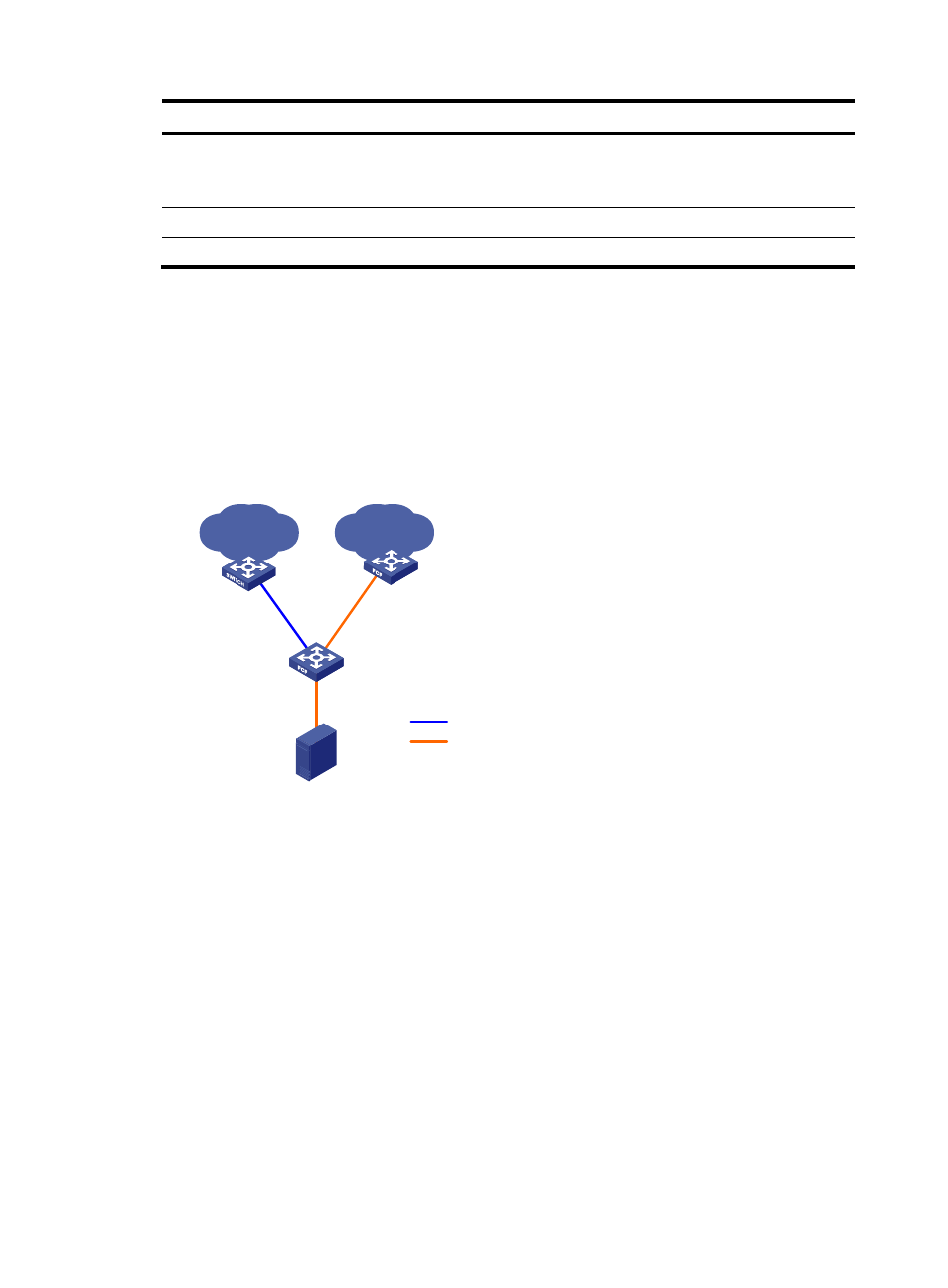
As shown in
, use the FCoE solution in a data center combining a LAN and a SAN to reduce
the number of devices, network adapters, and cables.
Figure 15 Network diagram
Configuration procedure
This section describes the configurations for VFC interfaces and FIP on the FCF switch.
1.
Configure Switch A:
# Configure Switch A to operate in advanced mode, save the configuration, and reboot Switch A.
(Skip this step if the switch is operating in advanced mode.)
<SwitchA> system-view
[SwitchA] system-working-mode advance
Do you want to change the system working mode? [Y/N]:y
The system working mode is changed, please save the configuration and reboot the
system to make it effective.
# Configure Switch A to operate in FCF mode, and create VSAN 10.
<SwitchA> system-view
[SwitchA] fcoe-mode fcf
[SwitchA] vsan 10
VFC1
XGE1/0/1
LAN
SAN
Ethernet
switch
FCF switch
FCF switch
Server
Ethernet
FCoE
VFC2
VFC2
XGE1/0/2
XGE1/0/2
Switch A
Switch B