Configuring ospf nsr, Network requirements, Configuration procedure – H3C Technologies H3C S10500 Series Switches User Manual
Page 137
122
%Dec 12 09:36:12:500 2006 SwitchA RM/3/RMLOG:OSPF-NBRCHANGE: Process 100, Neighbour
192.1.1.1(Vlan100) from Full to Down
OSPF 100: Intf 192.1.1.1 Rcv InterfaceDown State BackupDR -> Down.
OSPF 100 nonstandard GR Started for OSPF Router
OSPF 100 notify RM that OSPF process will enter GR.
OSPF 100 created GR wait timer, timeout interval is 40(s).
OSPF 100 created GR Interval timer,timeout interval is 120(s).
OSPF 100: Intf 192.1.1.1 Rcv InterfaceUp State Down -> Waiting.
OSPF 100: Intf 192.1.1.1 Rcv BackupSeen State Waiting -> BackupDR.
OSPF 100 created OOB Progress timer for neighbor 192.1.1.2.
OSPF 100 restarted OOB Progress timer for neighbor 192.1.1.2.
OSPF 100 restarted OOB Progress timer for neighbor 192.1.1.2.
%Oct 22 09:36:12:566 2008 SwitchA RM/3/RMLOG:OSPF-NBRCHANGE: Process 100, Neighbour
192.1.1.2(Vlan100) from Loading to Full
OSPF 100 restarted OOB Progress timer for neighbor 192.1.1.2.
OSPF 100 deleted OOB Progress timer for neighbor 192.1.1.2.
OSPF 100 Gr Wait Timeout timer fired.
OSPF 100 deleted GR wait timer.
OSPF 100 deleted GR Interval timer.
OSPF 100 GR Completed for OSPF Router
OSPF 100 notified RM that OSPF process left GR.
RM notified that all protocol left GR.
OSPF 100 started flushing STALE LSA after all protocol left GR.
OSPF 100: Flush Stale Area LSAs
OSPF 100: Start Flush Stale ASE + NSSA LSAs
OSPF 100: End Flush Stale ASE + NSSA LSAs
Switch A completes GR with the help of Switch B.
Configuring OSPF NSR
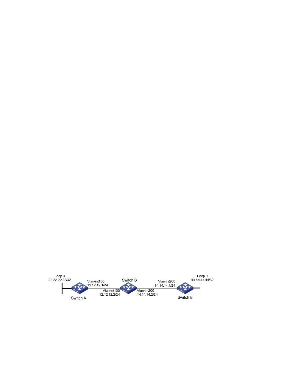
Network requirements
As shown in
, Switch S, Switch A, and Switch B belong to the same OSPF routing domain.
Switch S is a distributed device. Enable OSPF NSR on Switch S to ensure correct routing when an
active/standby switchover occurs on Switch S.
Figure 46 Network diagram for OSPF NSR configuration
Configuration procedure
1.
Configure IP addresses for the interfaces on each switch and configure OSPF.
Follow
to configure the IP address and subnet mask of each interface on the switches. (Details
not shown)