8939fcb modules, Attenuation requirements, Refer to – Grass Valley 8939FCA User Manual
Page 15
8939FCA/FCB — Instruction Manual
15
Installation
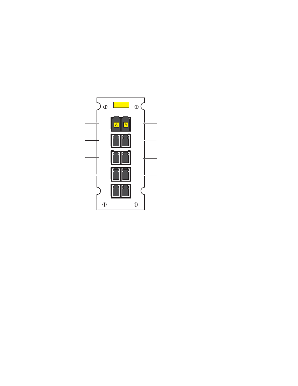
8939FCB Modules
The pinouts for the 8939FCB module are shown in
has eight fiber channels (CH 9 – CH 16), each handling a specific CWDM
frequency as silkscreened on the module.
the for cabling the COM and EXP
ports.
Figure 5. Current 8939FCB Backplane
Attenuation Requirements
Some shorter length cable runs will require attenuation to prevent over-
driving the receiver causing bit errors to occur on the fiber link. Use the fol-
lowing guidelines for adding attenuation:
•
The 1310nm Dual Transmitter (SFP-1310-SDTX) requires no attenuation
between the EXP ports at any cable lengths.
•
CWDM SFP devices used with 8939FCA modules for a mux/demux
configuration with cable runs from 0-12 km (7.5 miles), must be attenu-
ated by 3 dB between 8939FCA COM ports.
•
All CWDM SFP devices used in a point-to-point configuration with a
cable run from 0-20 km (12.4 miles), must be attenuated by 5 dB
between fiber transmitter and receiver connections.
8939FCB
1430nm input or output
1390nm input or output
1350nm input or output
1310nm input or output
CH10
1330nm
CH9
1310nm
CH11
1350nm
CH13
1390nm
CH15
1430nm
CH12
1370nm
CH14
1410nm
CH16
1450nm
EXP
COM
COM fiber optic connection
to 8939FCA module
1450nm input or output
1410nm input or output
1370nm input or output
1330nm input or output
N/A
8558_09
r0
Class IIIa
Laser Product