Grass Valley 8939FCA User Manual
Page 26
26
8939FCA/FCB — Instruction Manual
8939FCA and 8939FCB Applications
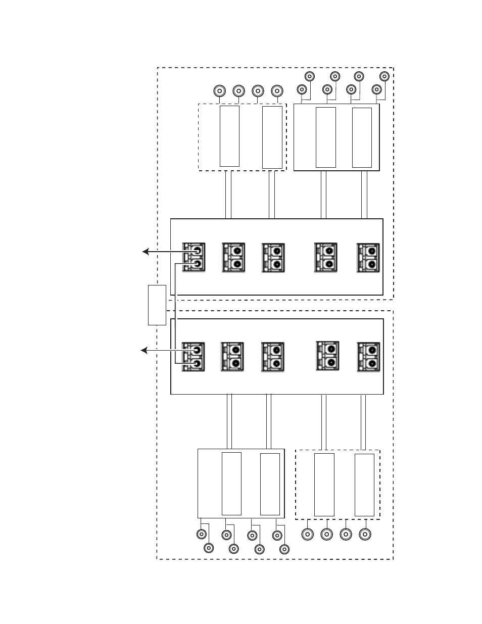
Figure 11. Bi-directional Application
8558_02r1
8939FCA
8943FC
Fiber Out
to 1610nm
Fiber Out
to 1610nm
Fiber Out
to 1610nm
Fiber Out
to 1610nm
Fiber Signal
from 1610nm
Fiber Signal
from 1590nm
Fiber Signal
from 1570nm
Fiber Signal
from 1550nm
Fiber Out
to 1530nm
Fiber Out
to 1490nm
Fiber Out
to 1470nm
Fiber Out
to 1510nm
Connector J4
Connector J6
8943CF
Fiber Signal
from 1530nm
Fiber Signal
from 1510nm
Fiber Signal
from 1490nm
Fiber Signal
from 1470nm
Connector J4
Connector J6
8943CF
Connector J4
Connector J6
Connector J4
Connecotr J6
SPF-13103G-M1DRX-K
1270 > 1610nm
SPF-13103G-M1DRX-K
1270 > 1610nm
SPF-13103G-M1DRX-K
1270 > 1610nm
SPF-13103G-M1DRX-K
1270 > 1610nm
8943FC
Location A
Location B
Ch1
In
Ch2
In
Ch3
In
Ch4
In
Ch1
In
Ch2
In
Ch3
In
Ch4
In
SFP-CWDM3G-4-K
1590nm & 1610nm
SFP-CWDM3G-4-K
1510nm & 1530nm
SFP-CWDM3G-4-K
1490nm & 1470nm
SFP-CWDM3G-3-K
1550nm & 1570nm
Ch1 Out
Ch2 Out
Ch4 Out
Ch3 Out
Ch4 Out
Note: In this configuration (8959CF
A to 8939CF
A utilizing CWDM transmitters), if the distance between 8939CF
A modules is l
ess than 12 km (7.5 m),
a 3 dB attenuator must be installed somewhere between the COM ports on the 8939CF
A modules to prevent overdriving the receiver
causing bit errors
to occur on the link.
*
COM
EXP
CH1
1470nm
CH2
1490nm
CH4
1530nm
CH3
1510nm
CH6
1570nm
CH6
1570nm
CH8
1610nm
CH8
1610nm
CH5
1550nm
CH7
1590nm
CH5
1550nm
CH7
1590nm
8939FCA
COM
EXP
CH1
1470nm
CH2
1490nm
CH4
1530nm
CH3
1510nm
Ch3 Out
Ch2 Out
Ch1Out
Connect to 8939FCB COM port for more channels
Distance of
up to 50km