Configuration switches s1 and s2, Figure 2, For using – Grass Valley 8949MDA-CXF User Manual
Page 12
12
8949MDA-CXF/-SXF — Instruction Manual
Installation
Configuration Switches S1 and S2
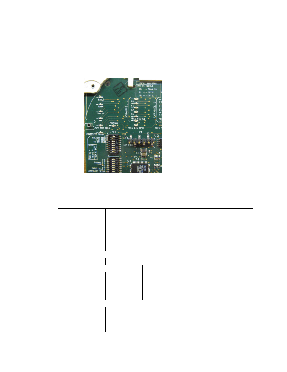
gives a photographic illustration of switches S1 and S2 and related
silkscreened information.
gives the parameters set with the
onboard switches S1 and S2 on the 8949MDA module circuit board.
Figure 2. Onboard Configuration Switches, S1 and S2
Note
Remote control settings made with the web interface will override local set-
tings. To lock out remote control, set the Config Mode to Off.
Table 1. Switch S1 and S2 Settings
Switch 1
Function
Pin
0 (Left/Off)
1 (Right/On)
Config Mode
1
Local mode (Remote control locked out)
Remote mode
Factory Mode
2
Off
Factory use only
Test Mode
3
Off
Factory use only
Tx Opt Mode
1
1
Fiber optic outputs are present when an optional Transmitter submodule (TX1 and TX2) or a Transceiver submodule (TX2) is installed.
4
Off (fiber optic outputs disabled)
On (fiber optic outputs enabled)
–
5-8
Not Used
Switch S2
–
1
Not Used
Format (Input)
Setting
Auto
1080i/50
1080i/59.94
720p/50
720p/59.94
480i/59.94
576i/50
2
0
0
0
0
0
0
0
0
3
1
0
0
0
0
1
1
1
4
2
0
0
1
1
0
0
1
5
3
0
1
0
1
0
1
0
Input Select
Setting
Coax In
Optic 1
Optic 2
6
0
0
0
1
7
1
0
1
0
Composite
Setup
8
Off
On