Non-heidenhain devices, Ethernet interface rj45 socket – HEIDENHAIN TNC 320 (340 551-02) User Manual
Page 465
Advertising
HEIDENHAIN TNC 320
465
14.2 Pin La
y
o
ut and Connecting Cable f
o
r the D
a
ta Int
e
rf
aces
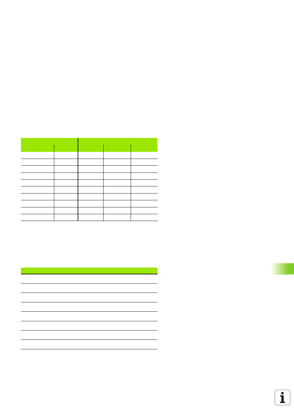
Non-HEIDENHAIN devices
The connector pin layout of a non-HEIDENHAIN device may differ
considerably from that on a HEIDENHAIN device, depending on the
unit and type of data transfer.
It depends on the device and the transfer mode. The table below
shows the connector pin layout on the adapter block.
Ethernet interface RJ45 socket
Maximum cable length:
Unshielded: 100 m
Shielded: 400 m
Adapter block 363 987-02
Connecting cable 366 964-xx
Female
Male
Female
Color
Female
1
1
1
RD
1
2
2
2
YL
3
3
3
3
WH
2
4
4
4
BN
6
5
5
5
BK
5
6
6
6
VI
4
7
7
7
GY
8
8
8
8
WH/GN
7
9
9
9
GN
9
Hsg.
Hsg.
Hsg.
Ext. shield
Hsg.
Pin
Signal
Description
1
TX+
Transmit Data
2
TX–
Transmit Data
3
REC+
Receive Data
4
Free
5
Free
6
REC –
Receive Data
7
Free
8
Free
Advertising