Reference system on milling machines, 1 f u ndam e n tals – HEIDENHAIN TNC 320 (340 551-02) User Manual
Page 55
HEIDENHAIN TNC 320
55
4.1 F
u
ndam
e
n
tals
Reference system on milling machines
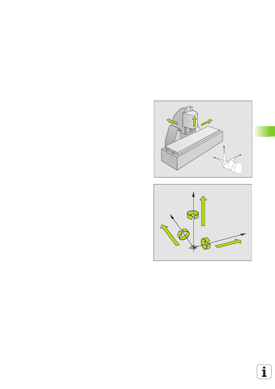
When using a milling machine, you orient tool movements to the
Cartesian coordinate system. The illustration at right shows how the
Cartesian coordinate system describes the machine axes. The “right-
hand rule” is illustrated for remembering the three axis directions: the
middle finger points in the positive direction of the tool axis from the
workpiece toward the tool (the Z axis), the thumb points in the positive
X direction, and the index finger in the positive Y direction.
The TNC 320 can control up to 4 axes (optionally 5). The axes U, V and
W (which are not presently supported by the TNC 320) are secondary
linear axes parallel to the main axes X, Y and Z, respectively. Rotary
axes are designated as A, B and C. The illustration at lower right shows
the assignment of secondary axes and rotary axes to the main axes.
+X
+Y
+Z
+X
+Z
+Y
W+
C+
B+
V+
A+
U+
Y
X
Z