3 installation, Type, Tightening torque – SMA CBL-DC-CMB1-10 User Manual
Page 16: Installation
CBL-DC-CMB1-10
16
PHOENIX CONTACT
106183_en_00
5.5.3
Installation
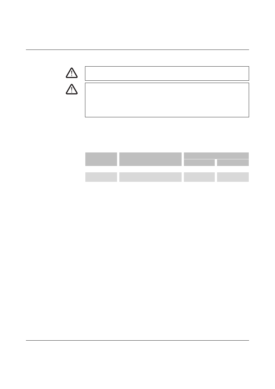
Torques for conductive connections
Before establishing the supply voltage and starting up for the first time, check all conductive
connections in the CBL-DC-CMB1-10. If necessary, retighten these connections using a
torque screwdriver taking into account the torque values. When doing so, observe the infor-
mation in the following table.
Connection
Installation must be performed by a skilled electrical engineer.
1.
Open the switching device combination.
2.
Release the cable entries.
3.
Guide the cables into the cable entries.
4.
Place filler plugs in unused cable entries.
5.
Tighten the cable entries.
6.
Strip the wires.
7.
Connect the conductors. When doing so, refer to the circuit diagram and the informa-
tion under “Connections” on page 17.
8.
Check and document the wiring.
9.
Close the switching device combination.
DANGER: Return of the supply voltage
Make sure that switching on the input voltage cannot lead to hazardous situations.
DANGER: Please observe the following when wiring inside the switching device
combination
–
Check the fuse protection inside the switching device combination.
–
If accessing the wiring, check the marking of the individual wires and the equipment
identification in accordance with the circuit diagram and check the contact assign-
ment in accordance with the switches and all other equipment.
BMK
Type
Tightening torque
Min.
Max.
-X1/2: -F1 ... -F12
UK 10,3-HESI 1000V
2 Nm
2.5 Nm
-X3: 1+ ... 3+
-X3: 4- ... 6-
STU 35/ 4X10
STU 35/ 4X10 BU
3.2 Nm
3.7 Nm
-X4: L+; L-
UKH 150/BU
25 Nm
25 Nm