Connections, 0 connections – Yaskawa F7 Drive Safe-Off Option User Manual
Page 10
Date: 10/15/07, Rev: 07-10
Page 8 of 12
TM.F7.03
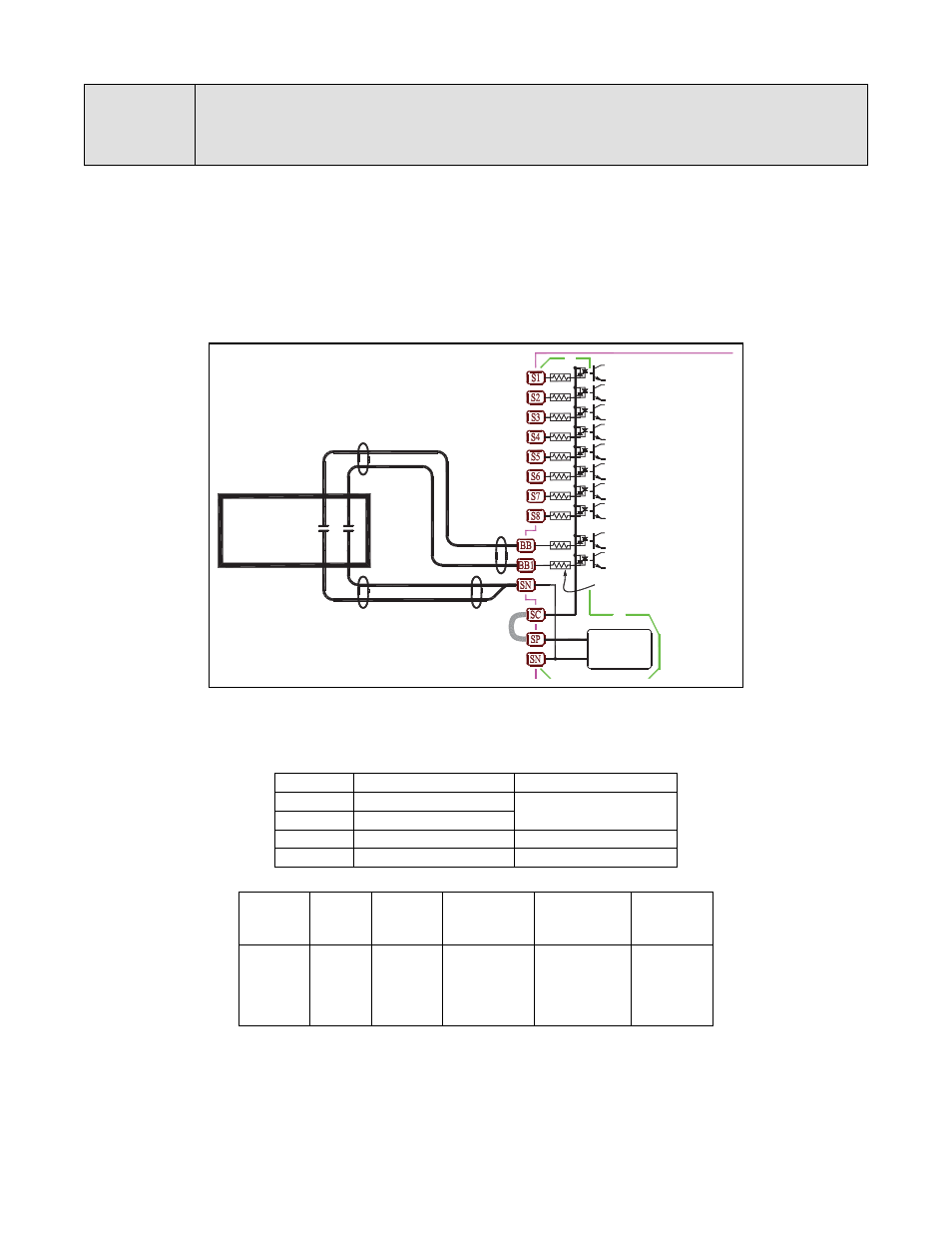
If the Safe-Off function is used, the factory-installed wire link (jumper) between terminals SN, BB and BB1 must be
removed entirely. Connect the drive to an EN954-1, Safety Category 3 interrupting device so that a Safe-Off
request breaks the connection between the terminal SN and both terminals BB and BB1. The normal connection is
shown below. Wires W
1
and W
2
should be run separately from W
3
and W
4
. A short circuit from W
1
or W
2
to W
3
and
W
4
would bridge the contacts of the safety device and nullify its operation.
To maintain the integrity of the safety system, no other control input should be connected to Safe-Off terminals BB
or BB1.
Normal Connection to EN954-1 Category 3 Safety Device
8.0
Connections
Safe Disable Terminals
No.
Signal Name
Signal Level
BB
Hardware Baseblock
24VDC, 8mA
photocoupler
BB1
Hardware Baseblock1
SN
Sequence input neutral
-
SC
Sequence input common
-
Terminals
Terminal
Screws
Tightening
Torque
(N•m)
Possible Wire
Sizes
mm
2
(AWG)
Recommended
Wire Size
mm
2
(AWG)
Wire Length
BB, BB1,
SC, SN
Phoenix
type
0.5 to 0.6
Solid wire:
0.14 to 2.5
Stranded wire:
0.14 to 1.5
(26 to 14)
0.75
(18)
50 m or less
BB = Hardware Baseblk
24VDC
(Isolated)
-
+
BB1 = Hardware Baseblk
H1-01 =
H1-06 =
H1-05 =
H1-04 =
H1-03 =
H1-02 =
Run Rev
Run Fwd
3.3K
Ω
24 (Ext Flt)
08 (Ext Baseblk)
06 (Jog Ref Sel)
03 (Ref Sel 1)
04 (Ref Sel 2)
14 (Clr Flt)
EN954-1
Category 3
Safety
Device
W
1
W
2
W
4
W
3