Changes from standard product, 0 changes from standard product – Yaskawa F7 Drive Safe-Off Option User Manual
Page 6
Date: 10/15/07, Rev: 07-10
Page 4 of 12
TM.F7.03
The Safe-Off option requires a special F7 control board (ETC 619320-S7160) and terminal board (ETC 619330)
which replace the standard drive control board and terminal board. The most salient difference is the ETC 619330
terminal board’s third row of control terminals containing the BB, BB1 and SN Safe-Off connections. The SN
Safe-Off terminal is electrically connected to the standard SN terminal.
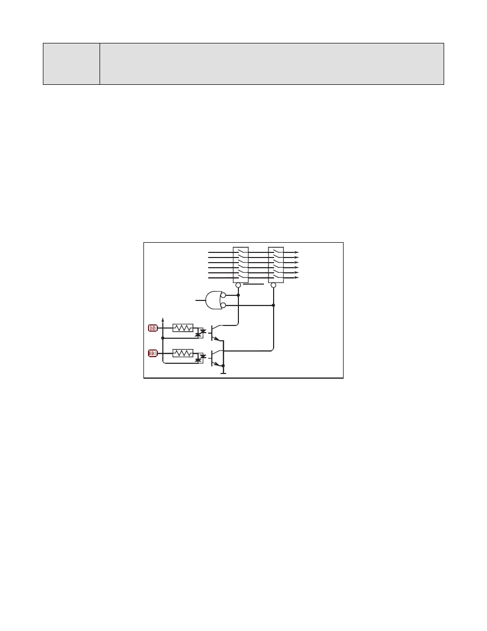
BB and BB1 have the same opto-coupler interface as the other digital inputs, S1 through S8, and operate from the
same isolated 24V on-board control supply. Whereas S1 through S8 connect only to the F7’s I/O processor, BB
and BB1 also connect to hardware buffers that can block the gate drive signals to the IGBTs and prevent the motor
from running.
The drive software interprets BB and BB1 exactly as a conventional “External Baseblock” command. Otherwise, all
standard F7 parameters and monitors retain their original functionality. In fact, multifunction digital inputs (S3
though S8) can still be programmed as conventional “External Baseblock N.O.” and “External Baseblock N.C.” to
maintain compatibility with previous utilizations.
Safe-Off Circuitry Blocks the IGBT Gate Signals Through Two Separate Hardware Channels
3.0
Changes From Standard Product
to IGBT
Gate Drivers
Gate Drive
Signals from
Processor
Enable
To Processor
SC