Acceleration ovp, Deceleration ovp, Decel time chart – Yaskawa G5 OV Suppression User Manual
Page 3
Date: 07/01/04, Rev: 04-07
Page 3 of 8
TM.G5SW.017
Acceleration OVP
The DC bus filter is used to provide a stable bus reference needed to determine sudden changes in the
DC bus. It should not fluctuate with short periods of regeneration. It also provides a floating threshold
that will adjust to normal AC line fluctuations. The filter buildup rate is controlled by P1-01: DC Filter Rise.
When the DC bus is above the filter + P1-03: Filter Deadband it will rise. The filter decrement rate is
controlled by P1-02: DC Filter Fall. When the DC bus is below the filter minus P1-03 the filter will fall.
The filter may be monitored via U1-51: DC Bus Filter. This filter should be setup to fall much faster than it
rises.
When the drive is running and the speed reference is constant the software monitors for DC Bus
Overshoot. The DC Bus Overshoot is the rise of the DC Bus that exceeds the sum of the DC Bus Filter +
P1-03: Filter Deadband. If this value is negative it is set to zero. U1-52: DC Bus Overshoot may be used
to monitor this value. The DC bus overshoot is multiplied by P1-04: OVP Fref gain and is converted into
a frequency reference. This reference may be monitored via U1-53: OVP Frequency and will be added to
the existing frequency reference. The result of this may be monitored via U1-54: Total Ref. Acceleration
will occur controlling regeneration into the inverter when there is a U1-52: DC Bus Overshoot value. The
rate of acceleration is controlled by C1-01: Accel Time 1. The inverter will return to the input speed
reference as the overshoot decreases. The rate of deceleration is determined based on the DC bus
voltage and typically will range from C1-02: Decel Time 1 to C1-06: Decel Time 3. This is covered in the
Deceleration OVP section.
Deceleration OVP
The deceleration OVP only functions when the speed reference is lowered. When the drive is stopped
the deceleration rate is set to C1-04: Decel Time 2. When the drive must decelerate after an overshoot
correction it will used the deceleration OVP value. C1-03: Accel Time 2 and C1-04: Decel Time 2 are
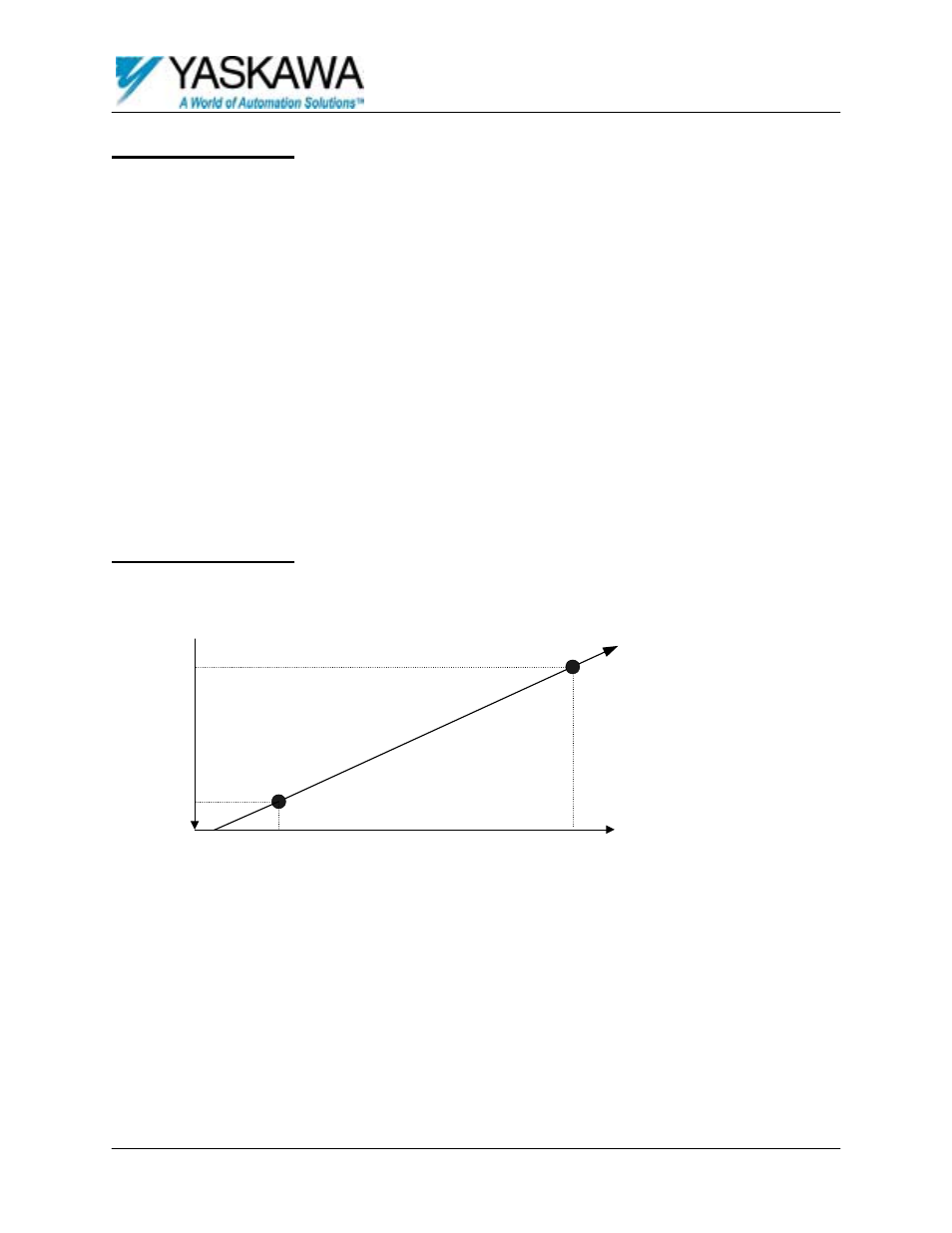
used by the drive for normal speed regulation. Above is a graphical representation of the deceleration
OVP portion of this software. At the DC voltage in P1-06: OVP Dec Start the deceleration rate will be the
value in C1-02: Decel Time 1. When the DC bus voltage rises above this level the deceleration time will
increase as indicated. The deceleration time will be at the value of C1-06: Decel Time 3 when the DC
bus voltage is equal to P1-07: OVP Dec Stop. The decel rate will change linearly along the slope defined
by the starting point C1-02: Decel Time 1, P1-06: OVP Dec Start and the second point C1-06: Decel Time
3, P1-07: OVP Dec Stop.
C1-02
Decel 1
C1-06
Decel 3
P1-06
OVP Dec Start
P1-07
OVP Dec Stop
Bus Volts
Decel
Time
100
700
750
20
Decel Time Chart