Yaskawa CM052 User Manual
Devicenet, Option card and ring kit cm052
Yaskawa Electric America, Inc –
www.drives.com
IG.V7.13, Page 1 of 5
Date: 07/01/04, Rev: 04-07
DeviceNet
TM
Option Card and Ring Kit
CM052
!
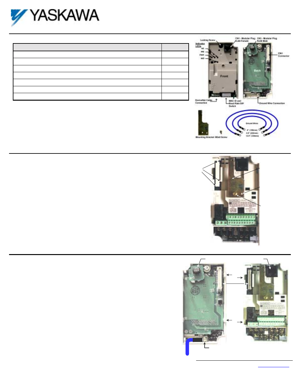
Unpack the V7 DeviceNet Option and verify that all components are present and undamaged.
Part
Qty.
V7 DeviceNet Option Card and Ring Kit
1
Mounting Bracket
1
M3×8 Screw
1
6” Ground Wire (150mm)
1
8.5” Ground Wire (220mm)
1
12.5” Ground Wire (320mm)
1
Installation Guide (IG.V7.13)
1
!
Connect power to the drive and verify that the drive functions correctly. This includes running the
drive from the operator keypad. Refer to the V7 Technical Manual, TM.V7.01, for information on
connecting and operating the drive.
!
Installing the V7 DeviceNet Option obscures the I/O, power and motor terminals on the V7 drive. It
is necessary to make these connections prior to installing the V7 DeviceNet Option. Check that all
connections have been made and are working correctly before continuing.
!
Remove power from the drive and wait for the charge lamp to be completely extinguished. Wait at
least five additional minutes for the drive to be completely discharged. Measure the DC BUS
voltage and verify that it is at a safe level.
!
Prepare the drive for the V7 DeviceNet Option.
# Remove the V7 operator keypad and terminal cover.
# Remove the plastic protective cover from over the CN2 connector and install
the option mounting bracket provided on to the drive.
!
Connect the ground wire provided to the ground connector on the back of the V7
DeviceNet Option. Select the ground wire of appropriate length for the drive.
!
Mount the V7 DeviceNet Option onto the drive
# Align the CN1 connector on the back of the option with its mating CN2
connector on the front of the drive.
# Simultaneously align the CN3 connector, the male RJ45 connector, on the back
of the option with the CN1 connector, the female RJ45 connector, on the front
of the drive.
# Align the tabs on the option with their corresponding slots on the front of the
drive.
# Press the option and the drive together until the tabs lock into their associated
slots.
# Secure the option to the V7 drive by tightening the locking screw at the top-
center of the option.
# Connect the ground wire from the V7 DeviceNet Option to ground terminal on
the V7 drive.
Align hole in
mounting bracket
with nib on front of
the V7 drive
Secure mounting
bracket to V7 drive
with M3x8 screw
Remove the CN2
protective cover by
carefully clipping
the three tabs
Option
mounting
bracket
CN2
C
o
v
e
r
CN1 - CN2
Tab
CN3 - Male RJ45
Connector
CN1 - Female
RJ45 Connector
Slot
Tab
Slot
E
Ground Terminal
Ground Wire