Yaskawa CM052 User Manual
Page 2
Yaskawa Electric America, Inc –
www.drives.com
IG.V7.13, Page 2 of 5
Date: 07/01/04, Rev: 04-07
!
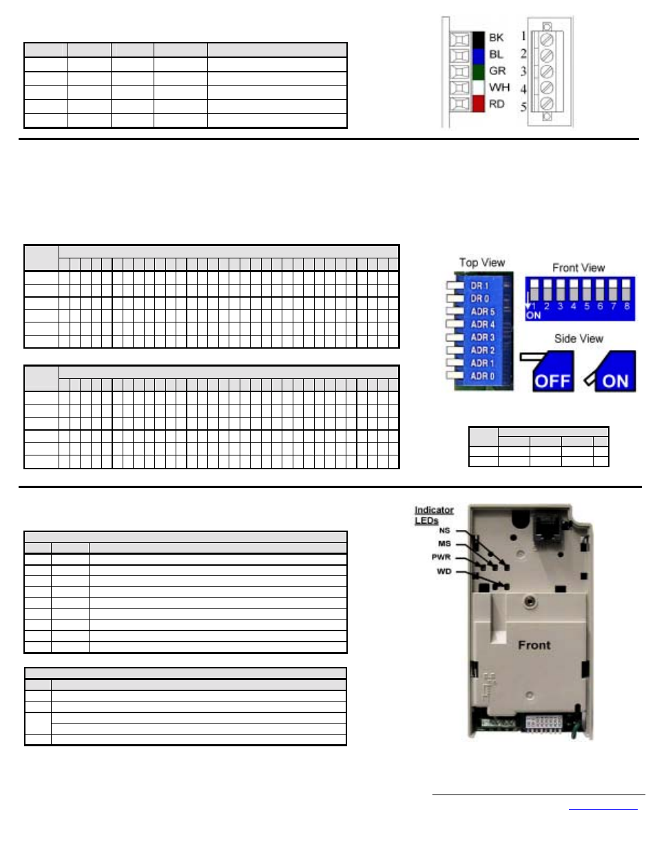
Connect to the DeviceNet network as shown in the figure to the right.
Terminal
Color
Name
Wire Color
Description
1 Black
V- Black
Communication
GND
2
Blue
CAN_L
Blue
CAN Data Low
3 Green Shield
Bare
Cable
Shield
4
White
CAN_H
White
CAN Data High
5 Red
V+
Red
Communications
+24Vdc
!
Set the V7DeviceNet Option Baud Rate
Set the Baud Rate for the V7 DeviceNet Option to the network baud rate by setting DIP switches DR1 (1) and DR0 (2) as shown in the figure below. The baud rate must
match the baud rate of the DeviceNet master (PC/PLC/Scanner) in order for the connection to function properly.
!
Set the V7 DeviceNet Option MAC ID
Set the MAC ID of V7 DeviceNet Option by setting DIP switches ADR 5 (3) through ADR 0 (8) as shown in the table below. Each device on the network must have a
unique MAC ID, typically between 3 and 62. Addresses 0 and 1 are usually reserved for DeviceNet masters, address 2 for diagnostic/monitoring equipment and address 63
for vendor specific functions in some systems. Check the network schematic to verify the MAC ID setting.
MAC ID
Sw
00 01 02 03 04 05 06 07 08 09 10 11 12 13 14 15 16 17 18 19 20 21 22 23 24 25 26 27 28 29 30 31
ADR 5 (3) 0
0
0
0
0
0
0
0
0
0
0
0
0
0
0
0
0
0
0
0
0
0
0
0
0
0
0
0
0
0
0
0
ADR 4(4) 0
0
0
0
0
0
0
0
0
0
0
0
0
0
0
0
1
1
1
1
1
1
1
1
1
1
1
1
1
1
1
1
ADR 3(5) 0
0
0
0
0
0
0
0
1
1
1
1
1
1
1
1
0
0
0
0
0
0
0
0
1
1
1
1
1
1
1
1
ADR 2(6) 0
0
0
0
1
1
1
1
0
0
0
0
1
1
1
1
0
0
0
0
1
1
1
1
0
0
0
0
1
1
1
1
ADR 1(7) 0
0
1
1
0
0
1
1
0
0
1
1
0
0
1
1
0
0
1
1
0
0
1
1
0
0
1
1
0
0
1
1
ADR 0(8) 0
1
0
1
0
1
0
1
0
1
0
1
0
1
0
1
0
1
0
1
0
1
0
1
0
1
0
1
0
1
0
1
0 = OFF
1 = ON
0 = OFF
1 = ON
MAC ID
Sw
32 33 34 35 36 37 38 39 40 41 42 43 44 45 46 47 48 49 50 51 52 53 54 55 56 57 58 59 60 61 62 63
ADR 5 (3) 1
1
1
1
1
1
1
1
1
1
1
1
1
1
1
1
1
1
1
1
1
1
1
1
1
1
1
1
1
1
1
1
ADR 4(4) 0
0
0
0
0
0
0
0
0
0
0
0
0
0
0
0
1
1
1
1
1
1
1
1
1
1
1
1
1
1
1
1
ADR 3(5) 0
0
0
0
0
0
0
0
1
1
1
1
1
1
1
1
0
0
0
0
0
0
0
0
1
1
1
1
1
1
1
1
ADR 2(6) 0
0
0
0
1
1
1
1
0
0
0
0
1
1
1
1
0
0
0
0
1
1
1
1
0
0
0
0
1
1
1
1
ADR 1(7) 0
0
1
1
0
0
1
1
0
0
1
1
0
0
1
1
0
0
1
1
0
0
1
1
0
0
1
1
0
0
1
1
ADR 0(8) 0
1
0
1
0
1
0
1
0
1
0
1
0
1
0
1
0
1
0
1
0
1
0
1
0
1
0
1
0
1
0
1
Baud Rate
Sw
125kbps 250kbps 500kbps N/A
DR1 (1)
0
0
1
1
DR0 (2)
0
1
0
1
!
Verify LED Status
Refer to the table on the following page for a complete listing of LED states.
LED Power-Up Sequence
LED
Color
Condition
PWR GREEN Steady
WD RED
On for 0.25 sec
WD NONE
Off for 0.25 sec
WD GREEN Blink at 0.1ms interval
MS GREEN On for 0.25 sec
MS RED
On for 0.25 sec
MS GREEN On for 0.25 sec
NS
GREEN On for 0.25 sec
NS
RED
On for 0.25 sec
LED normal operation Status
LED
Condition
PWR GREEN
MS GREEN
FLASH GREEN (no communication)
NS
REEN (communicating)
WD FLASH
GREEN