External encoder specifications, Smc–4000 installation guide – Yaskawa SMC-4000 User Manual
Page 17
13
SMC–4000 Installation Guide
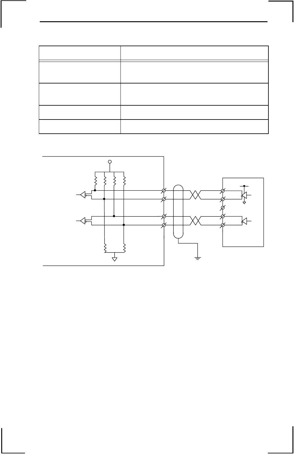
External Encoder Specifications
Standard voltage levels are TTL (0V to 5V), however, voltage levels
up to 12V are acceptable. If using differential 12V signals, no
modification is required. Single ended 12V signals require a bias
voltage applied to the complimentary input, i.e.; use two 10k resistors,
one connected to +12V and the other connected to the encoder signal
ground to hold the /A phase and /B phase at 6VDC. Do not use a
24VDC encoder.
Item
Specifications
Number of External
Encoders
One per Main Axis
Input Format
Quadrature or
Pulse and Direction
Maximum Frequency
12 MHz
Current Draw
940
µ
Amp
Internal Circuitry
VCC
3486
3486
4.
7
k
6.8
k
4.
7
k
6.
8k
2.
4
k
2.
4
k
Shield
12
37
23
11
Frame Ground
A+ phase
A- phase
B+ phase
B- phase
External Encoder
+5V or +12V
Field Wiring
X axis internal encoder shown
See 5CN connector for other axis pin connections.
SMC–4000 5CN Connector