Yaskawa VARISPEED-600 SERIES INVERTER User Manual
Page 36
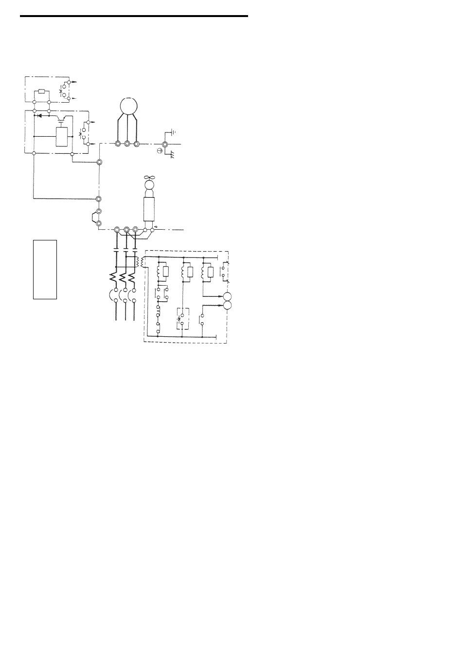
3. WIRING
37
©
R
MC
S
T
THRX
OFF
ON
MC
SA
12
MC
TRX
TRX
20
18
SA
SA
THRX
IM
VS
−
616G5
M
¨
1
¨
2
¨
3
P
1
2
3
4
B
MC
¨
0
©
0
¨
©
Overload
Relay
Trip
Contact
Level Detection
Braking
Unit
Braking
Resistor
Unit
(Option
)
Motor
Ground
(200V
Class
:100
Ω
or
less
400V
Class
:1
0Ω
or
less)
Cooling
Fan
L1
(R)
L2
(S)
L3
(T)
Short
−circuit
Bar
(Provided
as
Standard)
(ç
2
)
r(
ç
1
)
MCCB
Use
sequencer
to
break
power
supply
side
on
over-
load
relay
trip
contact
of
braking
resistor
unit.
3−
Phase
Power
Supply
380
to
460
V
50/60
Hz
Overload
Relay
Trip
Contact
of
Braking
Resistor
Unit
Fault Contact
Voltage Selection
460/440/415/ 400/380V
400/200V
U
(T1)
V
(T2)
W
(T3)
∗ 2
∼ ∼
∼ ∼
∗1
Where
∗
is
”E“
or
“V”.
∗2
When
using
the
braking
resistor
unit,
set
constant
L3
−04
to
“0”
(stall
prevention
selection
during
decel
is
disabled).
If
it
is
not
changed,
the
inverter
may
not
stop
within
set
decel
time.
Fig.
17
F
or
Models
CIMR
−G5
∗4018
to
−G5
∗4045
(400
V
Class
18.5
to
45
kW)