Yaskawa SmartTrac Digital User Manual
Page 12
SMART TRAC AC1
6
••
The Smart Trac AC1 Digital Operator Engineer's Guide Smart Trac Digital Operator
data including parameters, feedbacks and selection and use of special
functions.
•
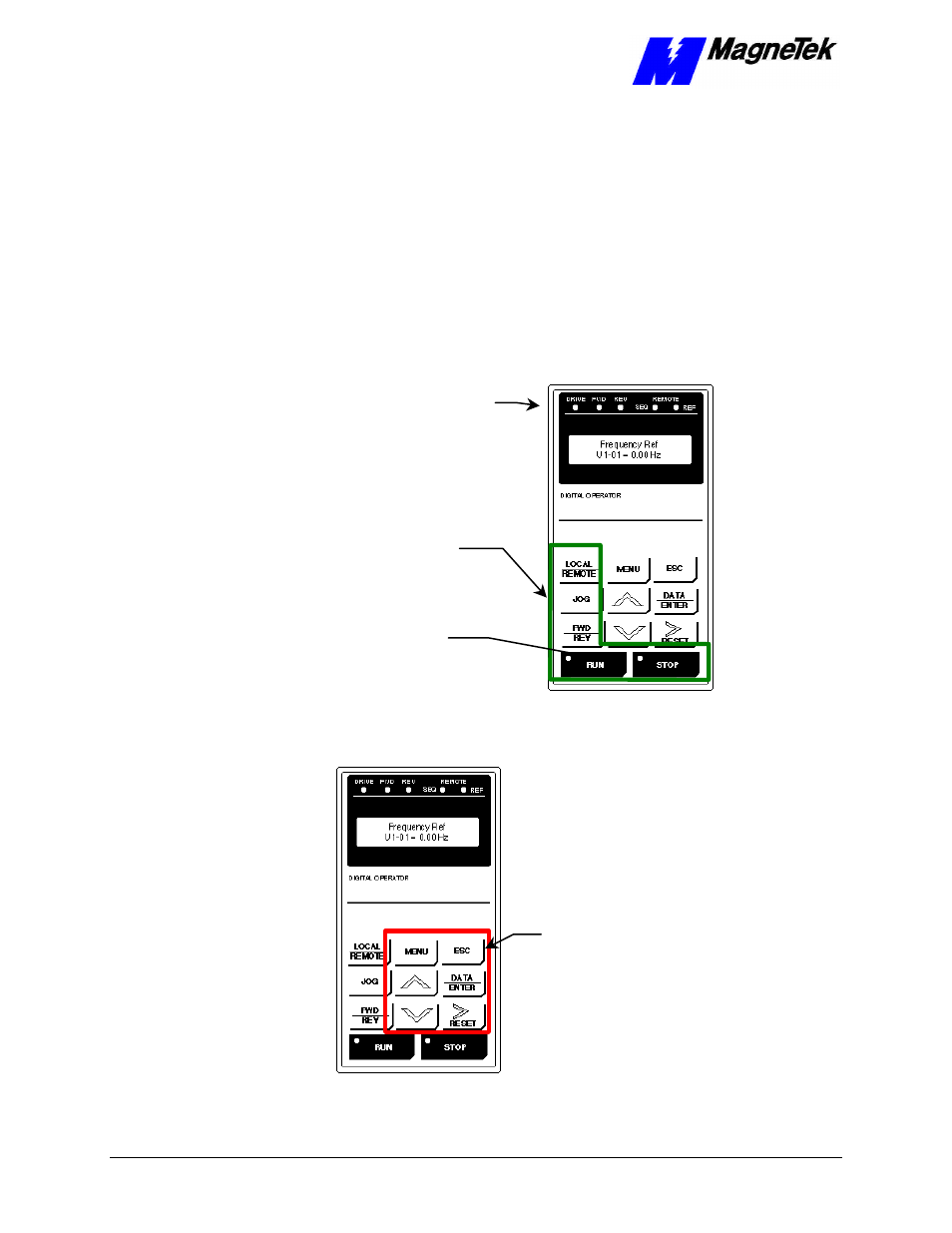
The CONTROL group includes the keys labeled LOCAL/REMOTE,
JOG, FWD/REV, RUN and STOP. These keys provide control over
the operation of the Smart Trac AC1. Although labeled for "typical"
use, they may be programmed to operate differently. Consult the
documentation specific to your Smart Trac AC1.
Indicators include seven status lights labeled DRIVE, FWD, REV,
REMOTE/SEQ and REMOTE/REF, RUN and STOP, and the LCD display
showing status, fault or parameter information. What causes these lights to be
triggered on or off is entirely up to the application program.
The behavior of each of these controls and indicators is described in tables and
the figures that follow:
Indicator
Lights
CONTROL
Group
RUN/STOP
Indicator
Lights in
Buttons
Figure 5.
The CONTROL Group of the Smart Trac AC1 Digital Operator.
DATA
Group
Figure 6
. The DATA group of the Smart Trac AC1 Digital Opertor.
Indicators