Connecting analog input pins, Single-ended analog inputs – Yaskawa SmartTrac DM6420 Multi I/O Card User Manual
Page 18
Smart Trac DM6420 Multi I/O Card
14
••
Configuring the Smart Trac DM6420 Multi I/O Card Technical Manual
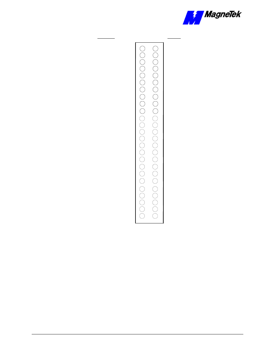
AIN1+ AIN1
AIN1- AIN9
AIN2+ AIN2
AIN2- AIN10
AIN3+ AIN3
AIN3- AIN11
AIN4+ AIN4
AIN4- AIN12
AIN5+ AIN5
AIN5- AIN13
AIN6+ AIN6
AIN6- AIN14
AIN7+ AIN7
AIN7- AIN15
AIN8+ AIN8
AIN8- AIN16
AOUT 1
ANALOG GROUND
AOUT 2
ANALOG GROUND
ANALOG GROUND
ANALOG GROUND
P0. 7
P1.7
P0. 6
P1.6
P0. 5
P1.5
P0. 4
P1.4
P0. 3
P1.3
P0. 2
P1.2
P0. 1
P1.1
P0. 0
P1.0
Unused
DIGITAL GROUND
Unused
Unused
Unused
Unused
Unused
Unused
Unused
Unused
Diff. S.E.
Diff. SE
1
3
5
7
9
11
13
15
2
4
6
8
10
12
14
16
17
19
21
23
25
27
29
31
33
18
20
22
24
26
28
30
32
35
37
39
41
34
36
38
40
42
43
45
47
49
44
46
48
50
Unused
DIGITAL GROUND
Figure 5.
Connector CN3 I/O Pin Assignments.
Connecting Analog Input Pins
You may set analog inputs for either single-ended or differential operation. You
must decide between differential or single-ended. A mix of differential and
single-ended is not permitted.
When operating in the single-ended mode:
1. Connect the high side of the analog input to one of the analog input
channels, AIN1 through AIN16.
2. Connect the low side to an ANALOG GND (pins 18 and 20-22 on
CN3).
Figure 6 shows how these connections are made.
Single-ended analog
inputs