Yaskawa V7 High HP User Manual
Page 7
Date: 03/29/05, Rev: 05-03
Page 7 of 8
TM.V7SW.026H
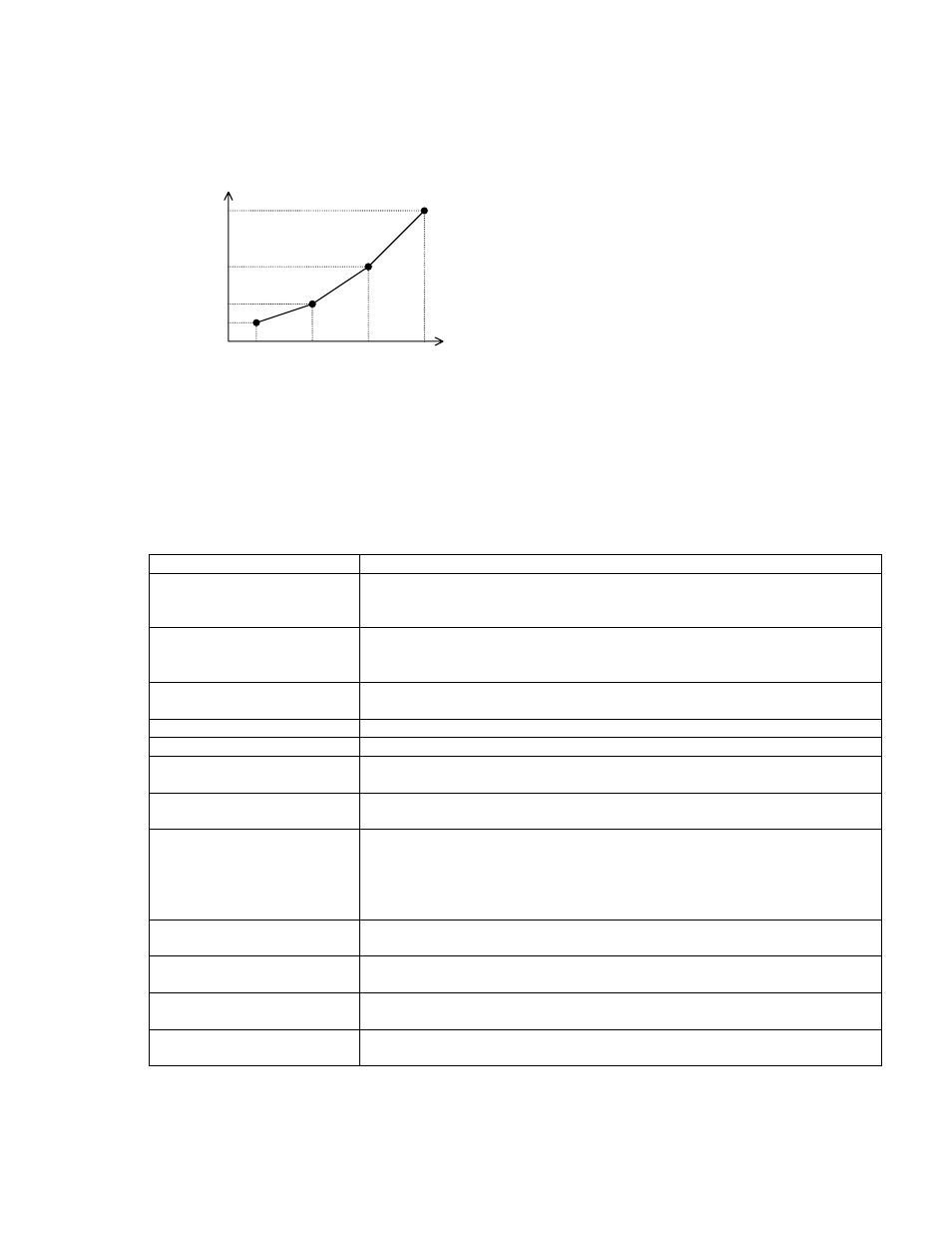
(8) V/f setting
Base frequency voltage (n045) is added. The V/f pattern is set as shown:
VMAX becomes effective at FMAX = FA.
(9) Deleted functions
The functions deleted from standard software are shown in the table below. The parameters
corresponding to these functions are deleted.
Deleted function
Deleted parameter/selection
Frequency reference from
operator CN2 terminal
Settings 7,8 of Frequency reference selection (n004)
Analog frequency reference gain, bias, and filter time constant (n068 ~
n073)
Frequency reference
setting/display
Unit selection
Unit selection for frequency reference setting/display (n035)
Frequency reference loss
detection
Reference loss detection selection (n064)
Pulse monitor output
Monitor output type selection (n065) and Pulse monitor scaling (n150)
Monitor item selection
Set point "3" and "4" of monitor item selection (n066)
Memobus frequency
reference/monitor unit
Setting 1 of Memobus frequency reference and frequency monitor unit
(n152)
Multi-function analog input
Multi-function analog input function, signal selection, frequency reference
bias value (n077 ~ n079)
PID control
PID control selection, feedback gain, proportional gain, integral time,
derivative time, offset adjustment, integral limit, primary delay time
constant, feedback loss detection selection, feedback loss detection
level/time, output gain, and feedback value selection (n128 ~ n138, n163,
n164)
Dynamic braking resistor
overheat protection
Dynamic braking resistor overheat protection selection (n165)
Input phase loss detection
Input phase loss detection level and input phase loss detection time
(n166, n167)
Output phase loss detection Output phase loss detection level and output phase loss detection time
(n168, n169)
Slip compensation
Motor rated slip, no-laod current, slip compensation gain/time constant
(n106, n110 ~ n112)
FOUT
VOUT
FMAX
FA
FB
FMIN
VMIN
VC
VA
VMAX
FOUT: Output frequency
VOUT: Output voltage after V/f conversion
FMAX: Maximum output frequency (n011)
VMAX: Mmaximum voltage (n012)
FA: Base frequency (n013)
VA: Base frequency voltage (n045)
FB: Mid. output frequency (n014)
VC: Mid. voltage (n015)
FMIN: Min. output frequency (n016)
VMIN: Min. voltage (n017)