Iqpump1000 simplex quick start procedure, Page 2 of 4 – Yaskawa iQpump1000 AC Drive User Manual
Page 2
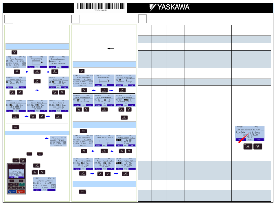
iQpump Quick Setup Parameter Overview (Simplex)
Step
5
Changing Parameters and
Monitoring the iQpump
Step
6
Application Setup
Step
7
Page 2 of 4
This step shows how to access and modify an iQpump parameter
as well as how to monitor iQpump signals such as output
frequency and motor current.
Make sure all protective covers have been re-attached and power
is turned on. DO NOT RUN THE MOTOR.
Press two times until the digital operator shows the parameter menu.
Select Digit
Access Parameter Menu and Change Parameter Value
Monitor Motor Frequency and Motor Current
Please refer to the iQpump Quick Start Guide, (Document No.
TOEP YAIP1W 01) on how to access other drive monitors.
2X
Inc./Dec. Selection
Inc./Dec. Selection
Go to Next Digit
Switch to Edit Mode
Save New Value
Modify Value
iQpump Digital Operator power-up state
Output Frequency and Transducer Feedback can be monitored
simultaneously.
Hold button for 3 sec. to go back to the main menu.
2X
Use and to select monitor signals.
Press simultaneously shows the monitor menu.
Use to select monitor.
Press to access monitor menu.
This step shows how to configure the iQpump for a dedicated pump
application.
Make sure all protective covers have been re-attached and power is
turned on. DO NOT RUN THE MOTOR.
Available iQpump Application Macro’s:
·
6008 Constant Pressure Mode (PSI)
·
6009 Pump Down Level Mode (Ft)
·
6010 Geothermal Mode
·
6011 VTC Pressure Control Mode
·
7770 General Purpose Mode
Press two times until the digital operator shows the parameter menu.
Select Digit
Select Application
2X
Inc./Dec. Selection
Select Application
Switch to Edit Mode
Press to select.
Hold button for 3 sec. to go back to the main menu.
2X
Enter Application Parameters
3X
Select Parameter.
Switch to Edit Mode
Save New Value
Modify Value
Hold button for 3 sec. to go back to the main menu.
Go Back to Main Menu
Default
The factory default is setup for
constant pressure PSI, only change if
application different.
Yaskawa America, Inc., 2121 Norman Drive South, Waukegan, IL 60085, (800) YASKAWA (927-5292) Fax (847) 887-7310, [email protected], www.yaskawa.com, Document Number: TM.TM.iQp1000.01 03/25/2013 © Yaskawa America, Inc.
Parameter
Value
Description
Reference
Comments
A1-06
Dependent on
Initialization
Mode
Application
Selected
Displays selected applications, see Step 6.
Read-only cannot be modified
E2-01
Drive Size
Dependent
Motor Rated Cur-
rent
Set to the motor nameplate full load amps.
For submersible motors use service
factor amps (SFA).
E2-04
2
Number of Motor
Poles
Number of motor poles is used to show the correct
motor RPM on the display
Enter ’4’ for an 1800 RPM motor and ‘2’ for a 3600
RPM motor.
Confirm number of poles
2 Pole Motor = 3600 RPM
4 Pole Motor = 1800 RPM
6 Pole Motor = 1200 RPM
8 Pole Motor = 900 RPM
P1-03 145
Feedback Device
Scaling
System Scaling: Enter feedback device maximum:
Example: Enter 200 for pressure transducer with a
maximum of 200 PSI at 20mA.
Confirm feedback device scaling.
(See Illustration 1)
Q1-01
0
Setpoint 1
Set System Setpoint
Set to system pressure
P1-04
0.0 PSI
Start / Drawn
Down Level
When the iQpump is turned On and the feedback
signal level (transducer) falls below this level, the
pump system will start after the time specified in P1-
05 (default 1 sec).
Programming the Start Level as an Absolute
Value. Start / Draw Down Level has to programmed
to a positive value in order for the Start / Draw Down
Level to be an absolute value. Example: Start /
Draw Down Level P1-04 set to 50 PSI and delay
time P1-05 set to 5 sec. Pump system will start
when the pressure drops below 50 PSI for 5 sec.
Programming the Start Level as a Delta Level
from the System Setpoint
Start / Draw Down Level has to programmed to a
negative value in order for the Start Level to be a
delta value from the setpoint.
Example: Start / Draw Down Level P1-04 set to –10
PSI with a system setpoint of 50 PSI and a delay
time P1-05 set to 5 sec. Pump system will start
when the pressure drops below 40 PSI (50 - 10) for
5 sec.
It is mandatory to program the Start / Draw
Down Level in order to use the sleep func-
tion.
(See Illustration 2 and 3)
P1-06
40.0 Hz
Minimum Pump
Speed
Minimum speed (Hz) the pump motor has to operate
at. Example: Base pump motor speed is 3600 RPM,
minimum speed is 2400 RPM. Set
minimum pump frequency to 40.0 Hz. (2400 ÷ 3600
x 60 Hz = 40 Hz)
Minimum pump frequency should be set to
a value where the pump enters a no-flow
condition.
P4-10
0
Disabled
Auto Mode Opera-
tor Run Power
Down
Storage
Stores the run status in the Auto mode when operat-
ing from digital operator (b1-02=0).
0: Disabled
1: Enabled
Recommended for use when Start/Stop
command is from the keypad.
(See Step 9)
P5-04
1
Enabled
Hand Key
Enable / Disable
Enables or disables the Hand Key on the digital op-
erator.
0: Disabled
1: Enabled
Hand Key on keypad.
(See Step 10)
Use
to change the sign.
iQpump1000
Simplex Quick Start Procedure