Iqpump1000 simplex quick start procedure, Page 3 of 4, Thrust bearing - submersible motors – Yaskawa iQpump1000 AC Drive User Manual
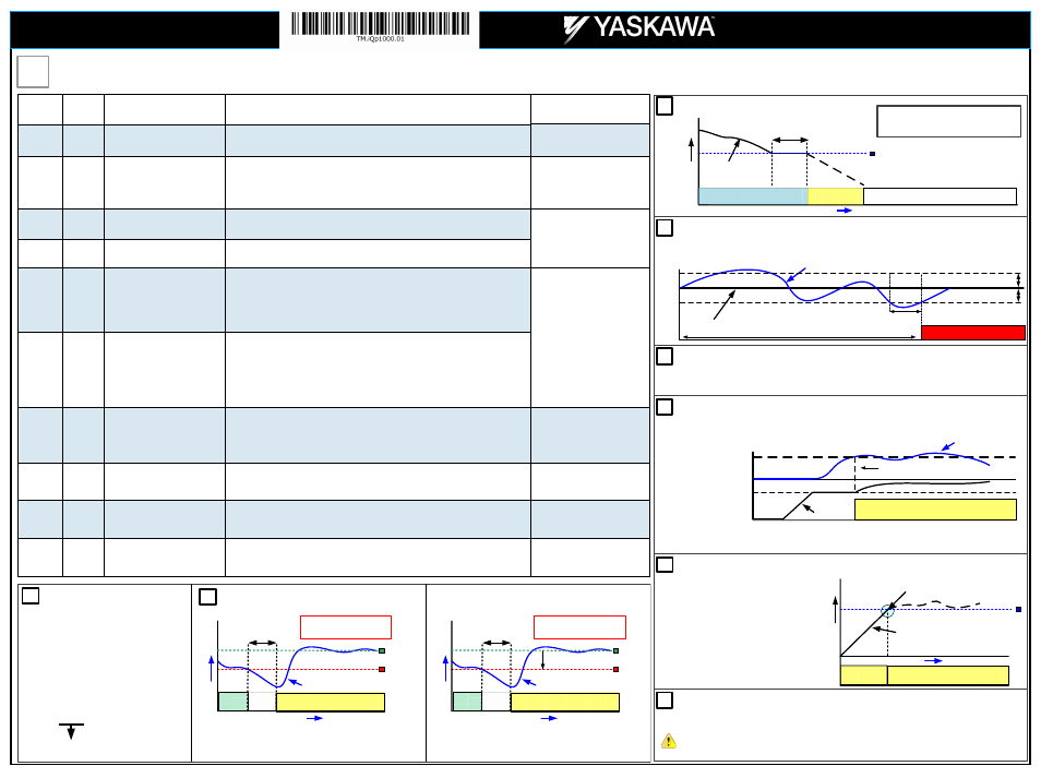
Page 3: Pump system fault setup pre-charge operation, Sleep mode (example), Pump running
Step
7
iQpump Factory Defaults Overview (only adjust settings based on your application)
Page 3 of 4
Yaskawa America, Inc., 2121 Norman Drive South, Waukegan, IL 60085, (800) YASKAWA (927-5292) Fax (847) 887-7310, [email protected], www.yaskawa.com, Document Number: TM.TM.iQp1000.01 03/25/2013 © Yaskawa America, Inc.
Parameter
Value
Description
Reference
Comments
b5-03
3.0 sec.
PI Integral Time
Decrease integral time to make iQpump more responsive.
Caution: can cause instability if
value is too low.
b5-12
2
(Fault)
PI Feedback Reference Missing
Detection Selection
Select what to do when the feedback device (transducer) fails or gets disconnected.
0: Disabled, continue running no message is displayed
1: Alarm, show warning on the keypad when the feedback device fails or is disconnected
2: Fault, stop pump system when the feedback fails or is disconnected
NOTE: Disable parameter b5-12
if no transducer is installed.
C1-01
20.0 sec.
See Note
Acceleration Time 1
Time it takes to accelerate the pump motor from zero to maximum speed.
NOTE: Factory default with Thrust Mode enabled is 12.0 sec, 20.0 sec when disabled.
Adjusted depending on system
performance
C1-02
10.0 sec.
See Note
Deceleration Time 1
Time it takes to decelerate the pump motor from maximum speed to zero.
NOTE: Factory default with Thrust Mode enabled is 5.0 sec, 10.0 sec when disabled.
L5-01
5
Number of Restart Attempts
Determines the number of times iQpump will perform an automatic restart on the faults listed
in the comments column.
iQpump System Protection Faults that can be setup to restart are Low Level Feedback,
High Level Feedback, Transducer Loss, Not Maintaining Setpoint, Loss of Prime,
Pump Over Cycle. Refer to parameters P4-07 and P4-08. The number of restart attempts is
set by L5-01.
x
Overcurrent
x
Ground Fault
x
Output Phase Loss
x
Input Phase Loss
x
iQpump Overload
x
Motor Overload
x
Overtorque
x
DC Bus Fuse Blown
x
DC Bus Undervoltage
x
DC Bus Overvoltage
x
Overheat
L5-03
20 sec.
Maximum Restart Time After Fault
If the restart fails (or is not attempted due to a continuing fault condition) iQpump waits the
Maximum Restart Time After Fault, before attempting another restart.
P1-06
40.0 Hz
Minimum Pump Frequency
Minimum speed (Hz) the pump motor has to operate at.
Example: Base pump motor speed is 3600 RPM, minimum speed is 2400 RPM. Set minimum
pump frequency to 40.0 Hz. (2400 ÷ 3600 x 60 Hz = 40 Hz)
P1-06 should be set to the level
where the pump can produce the
minimum pressure even at zero
flow.
P2-03
5 sec.
Sleep Delay Time
Time it takes before the pump system goes to sleep when the selected signal level (P2-01)
falls below the specified sleep level (P2-02)
Adjust according to system
requirements.
P4-12
30.0 Hz
Thrust Bearing Frequency
Sets the frequency reference used when the thrust bearing function is active. A value of 0
disables this function.
Primarily used for submersible
pumps. Program P4-12 = 0.0 Hz
to disable function when iQpump is
used with a centrifugal pump.
P4-17
0.2 Min
Utility Start Delay
When utility power is restored and P4-10 is enabled (1), iQpump waits the time specified in
P4-11 before auto operation becomes active.
Note: Only active when P4-10 is
enabled (1) and operation
(start/stop) is from the
digital operator.
THRUST BEARING - SUBMERSIBLE MOTORS
When u
using a submersible motor in combination
with the iQpump, it is recommended to use the
Thrust Bearing function to prevent excess motor
wear. To enable this function, enter the minimum
motor frequency in parameter
P4-11. Example: Minimum motor speed 1800
RPM, 1800 RPM ÷ 3600 RPM x 60.0 Hz = 3
30.0 Hz
Output Frequency
Output Frequency
Thrust Bearing Frequency P4-12
(Example 30.0 Hz)
Time
Thrust
Bearing
Auto/Hand Operation
Turn Off Thrust Bearing Function
(Output Frequency Reached)
P4
-0
4
A
cc
el
. T
im
e
Thrust Acceleration Time P4-11
(Example 1.0 sec.)
C1-01 Acceleration Time
PUMP SYSTEM FAULT SETUP
PRE-CHARGE OPERATION
5
4
6
7
LOW/HIGH FEEDBACK LEVEL DETECTION
AUTO OPERATION – POWER DOWN STORAGE
8
Allows iQpump to automatically start after power failure when operated from keypad / digital operator. This function is
recommended for use when operating the iQpump in remote / unmanned areas. Use parameter P4-10 to enable.
When the iQpump is powered down while running, an internal run
command will automatically be initiated upon power-up.
This function is used when the pump system requires to be pre-charged before normal operation. Upon start the
iQpump will run at a fixed speed for a specified time or until the feedback signal reaches a programmed level after
which it will switch to auto mode operation.
Feedback
0 Hz
Pre-Charge Freq. P4-02
Pre-Charge Completed
Pre-Charge Lvl. P4-01
P4-01 Pre-Charge Level: Specified feedback level to stop pre-charge operation
P4-02 Pre-Charge Frequency: Set desired pre-charge speed
P4-03 Pre-Charge Time: Specified maximum pre-charge operation time
FEEDBACK SIGNAL
P1-11
Time
SETPOINT
SET-POINT NOT MET
P1-16
Setpoint-LOP Tim
The iQpump can display a ‘S
Setpoint Not Met’ fault when the iQpump is unable to maintain the programmed system
setpoint due a problem with the pump system. Set P1-15 to the maximum allowed difference between setpoint and
feedback level.
P1-11
P1-15 Max Setpoint Diff
iQpump continuously monitors the system feedback signal. To display a ‘L
Low Feedback’ fault set the low feedback
level parameter P1-08 to the minimum feedback level allowed for your system and to display a ‘H
High Feedback’ fault
set the high feedback level parameter P1-11 to the maximum feedback level allowed.
Auto Operation
Output
Frequency
SLEEP MODE (Example)
Minimum Speed P1-06
(Example 40.0 Hz)
Output Frequency
(pump motor speed)
0
Sleep Delay Time (P2-03)
(Example 5.0 sec.)
Ramp or Coast to Stop, b1-02
Output Frequency
60 Hz
Pump Running
Go to Sleep
Time
WAIT FOR PRESSURE TO FALL BELOW
START / DRAW DOWN LEVEL (P1-04)
SYSTEM GOES TO SLEEP WHEN PUMP
MOTOR SPEED DROPS BELOW 40 Hz
(2400 RPM for 3600 RPM Motor).
3
P1-03 = 200.0 PSI Feedback Scaling
P1-02 Feedback Unit
0: Inch of Water
8: Bar
1: PSI
9: Pascal
2: GPM
10: Degrees Celsius
3: Degrees Fahrenheit
11: Meter
4: CFM
12: Feet
5: CMH
13: Liters per Minute
6: Liters / Hr
14: cm per Minute
7: Liters/Sec
15: Inch Hg
25: No Unit
Feedback
Maximum
SYSTEM FEEDBACK UNIT /
FEEDBACK DEVICE SCALING
1
START / DRAW DOWN LEVEL
Start Pump System
Start
Delay
200
PSI
Start / Draw Down Level (P1-04)
(Example 100.0 PSI)
System Setpoint
(Example 150.0 PSI)
Feedback Signal from pressure
transducer (4 – 20 mA)
0
Time
Pressure
Start Level Delay (P1-05)
(Example 5.0 sec.)
System Units (P1-02)
(Example PSI)
Feedback Scaling (P1-03)
(Example 200.0 PSI)
WAIT
2
SYSTEM STARTS WHEN
PRESSURE SIGNAL FALLS
BELOW 100 PSI
Example: Absolute Level (Positive Start Level)
Example: Delta Level (Negative Start Level)
150
Start Pump System
Start
Delay
Start / Draw Down Level (P1-04)
(Example -50.0 PSI, (150.0 – 50.0)
System Setpoint
(Example 150.0 PSI)
Feedback Signal from pressure
transducer (4 – 20 mA)
Time
Pressure
Start Level Delay (P1-05)
(Example 5.0 sec.)
System Units (P1-02)
(Example PSI)
Feedback Scaling (P1-03)
(Example 200.0 PSI)
WAIT
SYSTEM STARTS WHEN
PRESSURE SIGNAL FALLS
BELOW 100 PSI
-50.0 PSI
150
200
PSI
START / DRAW DOWN LEVEL
iQpump1000
Simplex Quick Start Procedure