iSys V8.5e Thermal Printer User Manual
Page 58
58
B. APPENDIX
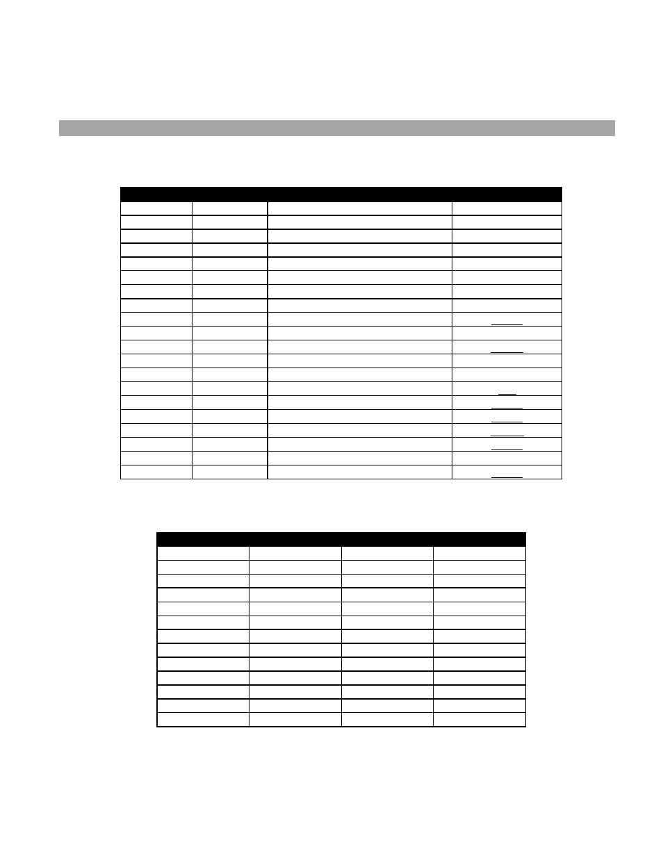
INTERFACE CONNECTOR PIN ASSIGNMENT
Signal Pin
Return Pin
Signal Name
Mnemonic
1
20
Input Bit 1 (LSB)
INDI 1
2
21
Input Bit 2
INDI 2
3
22
Input Bit 3
INDI 3
4
23
Input Bit 4
INDI 4
5
24
Input Bit 5
INDI 5
6
25
Input Bit 6
INDI 6
7
26
Input Bit 7
INDI 7
8
27
Input Bit 8 (MSB)
INDI 8
9 28
Clear
CLEAR
10
29
Parallel Input Clock
PICLK
11 30
Ready
READY
12 31
13
Not
Connected
NC
14
33
Simultaneous Plot / Print
SPP
15 34
Remote
Reset
RESET
16
35
Remote Form Feed
RFFED
17
36
Remote End of Transit
REOTR
18 37 Remote
Line
Terminate
RLTER
19 37
No
Paper
NOPAP
32 37
Online
ONLIN
Table B-1. Versatec cable pin outs (straight through)
Pin
Signal
Pin
Signal
1 STROBE 14 AFXT
2 DATA
0 15 ERROR
3 DATA
1 16 RESET
4 DATA
2 17 SLCTIN
5 DATA
3 18 GND
6 DATA
4 19 GND
7 DATA
5 20 GND
8 DATA
6 21 GND
9 DATA
7 22 GND
10 ACK 23 GND
11 BUSY 24 GND
12 PE 25 GND
13 SLCTOUT
Table B-2. Centronics cable pin outs (straight through)