Bang & Olufsen BeoLab Transmitter 1 User Guide User Manual
Page 6
Connect to a Bang & Olufsen television …
– Set the B&O INPUT switch to YES.
– Fill up the PL sockets on your transmitter from
the left (PL1) to the right with a subwoofer as
the last to connect.
Connect the cables …
> Make sure the television and transmitter are
disconnected from the mains.
> Connect two speaker signals at a time by
connecting one end of a Power Link cable to the
PL1 socket on the transmitter and the other end
to a Power Link socket on the television.
> Continue to connect Power Link cables by filling
up the PL sockets on your transmitter from the
left until all speakers signals are connected.
> Connect the television, the transmitter, and the
speakers to the mains. The transmitter’s wireless
status indicator starts flashing white, the
product status indicator on the front panel
becomes solid red for some seconds before
switching off, and the speakers’ wireless status
indicators start flashing green.
When Power Link sockets on your television are
predefined …
Fill the PL sockets on the transmitter from the left
to the right, remember to connect a subwoofer to
the last of the used PL sockets. Note down which
socket you connect to on the television, for
example:
Contact your retailer to get the correct cables.
If only the subwoofer and centre speaker sockets
are predefined on the television, 1(SUB) should
always be chosen for the last PL socket on the
transmitter to be connected, having in mind the
sockets are filled from the left.
Wireless sound
When you switch on a source, it takes several
seconds before sound is heard in the speakers,
during which time a stable wireless connection is
established between the transmitter and speakers.
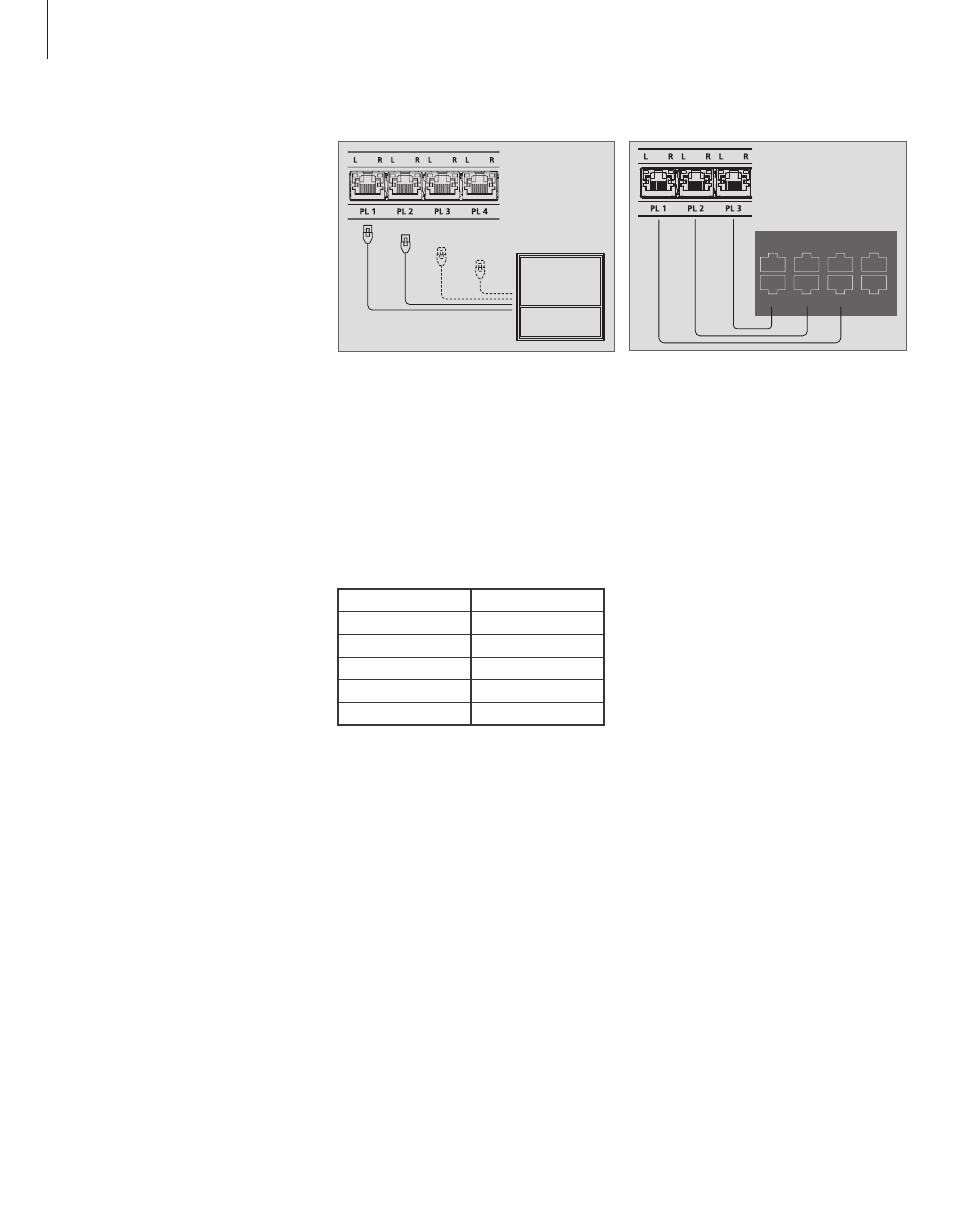
Television sockets
Transmitter sockets:
Left REAR
PL1
Right REAR
PL1
Left FRONT
PL2
Right FRONT
PL2
SUB
PL3
PL 5
PL 4
MONITOR
CONTROL
PUC 2
A+B
PL 3
PL 2
PL1 PUC 3 A+B
CTRL 3
6
Fill up the PL sockets from the left (PL1) to the right.
Four Power Link cables are shown here, which is a
full 7.1 setup
Example of cable connection between the
transmitter box and a television.