Command 7: status check – Casio EA-200 Technical Reference User Manual
Page 16
– 16 –
Command 7: Status Check
{ 7 }
After Command 7 is received, this function sends EA-200 status information upon a data request from the calculator.
Status Request
Line
1
Basic Information
Status
0: Standby
(No Sample Data in EA-200)
1: Ready
2: Sampling
3: Standby
(Sample Data in EA-200)
2
Error
= 0: Normal
Code
≠ 0: Error
Integer:
Command number
Decimal Part:
Parameter position
Example: 3.2
Command 3 is the
second parameter.
Sampling interval value
error
3
Battery
0 to 999
Condition
< 450: low battery
4
Version No.
5
Auto-ID
CH1
6
CH2
7
CH3
8
SONIC
9
Channel 1 Setup
Operation
10
Pin No
11
Post-Processing
12
Trigger Edge
13
Trigger Threshold
14
Sampling Range Maximum Value
15
Sampling Range Minimum Value
16
Equation Number
17
Number Format
18
Number of Constants
19
Constants K
0
:
:
28
Constants K
9
29
Channel 2 Setup
Operation
30
Pin No
Line
31
Channel 2 Setup
Post-Processing
32
Not used
33
Not used
34
Sampling Range Maximum Value
35
Sampling Range Minimum Value
36
Equation Number
37
Number Format
38
Number of Constants
39
Constants K
0
:
:
48
Constants K
9
49
Channel 3 Setup
Operation
50
Pin No
51
Post-Processing
52
Not used
53
Not used
54
Sampling Range Maximum Value
55
Sampling Range Minimum Value
56
Equation Number
57
Number Format
58
Number of Constants
59
Constants K
0
:
:
68
Constants K
9
69
Channel SONIC
Operation
70
Setup
Pin No
71
Post-Processing
72
Trigger Edge
73
Trigger Threshold
74
Equation Number
75
Number Format
76
Number of Constants
77
SONIC filter
78
Constants
79
Not used
:
87
88
Channel DIG IN
Operation
Setup
89
Channel DIG
Data String Output Loops
90
OUT Setup
Loop Counter
91
Number of Data String
• Last error code: 0 = no errors
An error causes a 3-digit error code to appear on the display. The
first digit indicates the command number, while the remaining two
digits indicate the parameter where the error occurred (i.e. first
parameter is indicated by 01, second indicated by 02, and so on).
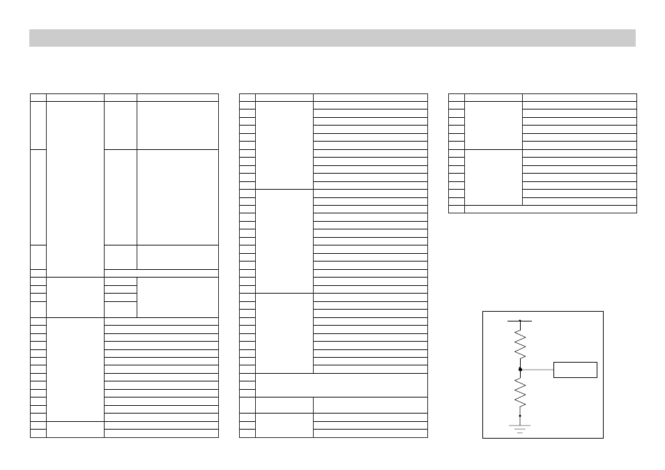
• Auto-ID resistance value (Ω) for CH1, CH2, CH3, and SONIC
A reading in the vicinity of 999 kΩ indicates that the applicable
channel is open.
• List of all active channels (Variable)
0 to 1023
Calculation Method:
(See circuit diagram)
1023(bit)×R÷(R+10(kΩ))
R:Auto-ID(kΩ)
Line
92
Channel Analog
Data String Output Loops
93
Out or Speaker
CH3 or Speaker
94
Setup
Data Output Selection
95
Number of Steps 1,2,4,8,16
96
Loop Counter
97
Number of Data String
98
Sample and
Sampling Interval (sec)
99
Trigger Setup
Number of Samples
100
Record Time
101
Clock Source
102
Trigger Source
103
Trigger Edge
104
Trigger Threshold
105 Not used
10-bit A/D
Converter
3.0V
10k
Ω
Auto-ID
Circuit Diagram