Analog sampling, Memory – Casio EA-200 Technical Reference User Manual
Page 3
– 3 –
Analog Sampling
Channel Names: CH1, CH2, CH3
1. CH1, CH2, CH3 Connector Specifications
Pin Number
1
Vin
Ϯ10V (CH3: VinϮ5V and Ϯ3Vout)
2
GND
3
Vres
4
Auto-ID
5
+5.3V DC
6
Vin-low 0–5V
2. Types of Sampling
1 Voltage
Two sampling ranges are shown below.
•
Ϯ10V 1pin (CH3: Ϯ5V)
• 0 to 5V Pin 6
2 Resistance
Two sampling ranges are shown below.
• pin6: 1–100kΩ
• pin4: Auto-ID
3 Pulse period
Two sampling ranges are shown below
•
Ϯ10V 1pin (CH3: Ϯ5V)
• 0 to 5V Pin 6
For details, refer to “Pulse Sampling” on page 4.
Pin 5 +5.3V Power Supply
Supplied from 100 msec before Clock Source.
Variable using power supply command (Command 10).
5pin
Power supplied during ready state.
Sampling Interval
100msec
Memory
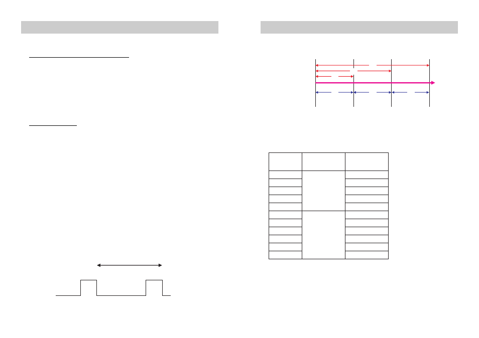
1. Sampling Time Data
<Absolute Time and Relative Time>
2. Number of Sample Data
Number of Sample Data: 120000
• Number of Sampling Channels and Number of Sample Data
Absolute Time
Relative Time
T2
T3
T4
T2
T3
T4
( T1=0 )
Time Axis
Trigger Source
Sample Value 1
Clock Source 1
Sample Value 2
( T1=0 )
Clock Source 2
Sample Value 3
Clock Source 3
Sample Value 4
* The number of samples is 2^n when FFT Samples (n) is used.
Number of
Sampling
Channels
Clock Source
Maximum
Number of
Sample Data
1
Clock Source =
Timer
120000
2
60000
3
40000
4
30000
5
24000
0
Clock Source =
External Trigger
60000
1
40000
2
30000
3
24000
4
20000
5
17140
The maximum number of
sample data when a timer
is the sampling trigger is
calculated using the
following formula:
120000
Ϭ[Number of
Channels Used]
The maximum number of
sample data when an
external trigger is the
clock source is calculated
using the following
formula:
120000
Ϭ([Number of
Channels Used] + 1)