Kichler 2218 User Manual
Kichler Lighting
Date Issued: 7/15/05
IS-2218-CB
P
L
X
M
N
W
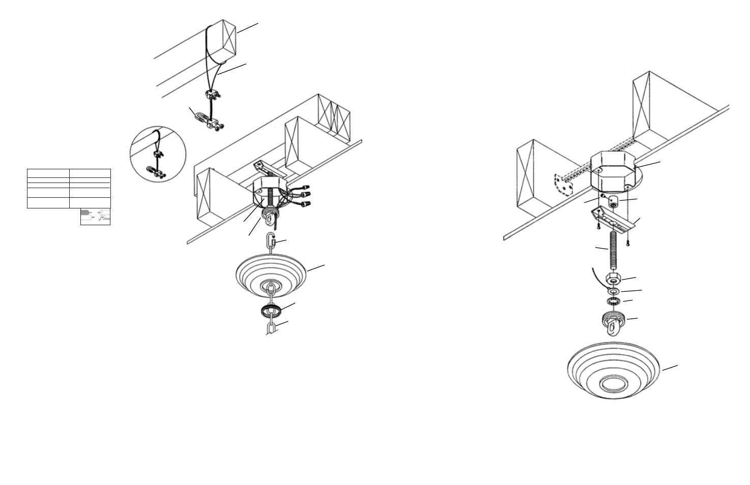
SAFETY CABLE
CÂBLE DU SUPPORT
STRUCTURAL BRIDGING MEMBER
POUTRE TRAVERSIÈRE DE FORCE
CLAMP
SERRE-CÂBLE
(T)
3
1) Turn off power.
2) Attach chain to fixture. Fixture loop has one chain link factory installed.
Chain has one locking link at each end. Unscrew coupling on locking
link and slip over link attached to loop. Screw coupling closed.
3) Slip threaded ring (N) then canopy (M) onto chain (W)
4) Attach chain (with fixture connected) to bottom of screw collar
loop following the same procedure as in step 1.
5) Weave electrical wire, ground wire and safety cable through
chain links no more than 3 inches apart.
6) Pass electrical wire ground wire and safety cable
through threaded ring (N), canopy (M), one of the
slots in screw collar loop (L) and into outlet box.
7) Pass safety cable through hole (See sec. 1)
8) In area above outlet box wrap cable around one
of the 2 x 4’s erected in section 1 and pull cable taut..
9) Secure cable with (2) clamps provided.
NOTE: Cable is not to be used as the only means of
fixture support. Please follow independent mounting
instructions completely.
10) Connect fixture ground wire and ground wire attached
to threaded rod (B or P) to outlet box ground
wire with wire connector (not provided).
Never connect ground wire to black or
white power supply wires.
11) Make wire connections (connectors
not provided). Reference chart below
for correct connections and wire
accordingly.
12) Raise canopy (M) to ceiling.
13) Secure canopy (M) in place by screwing threaded ring (N) onto screw
collar loop (L)
NOTE:
NEC CODE (314.24) requires that ceiling outlet boxes in the United States support up
to 50 lbs. This fixture exceeds 50 lbs. and must be installed using an outlet box approved for
up to 100 lbs. or independently of the existing outlet box. Installation hardware and instruc-
tions are provided for both.
MOUNTING TO A 100 lb. MAX. APPROVED OUTLET BOX
1)
Support cable from fixture (see sec. 3) must pass through outlet box. Drill 3/16” diameter
hole in outlet box if no other holes are available.
2)
Screw threaded rod (B) from parts bag into pipe coupling (A) until threaded rod is flush
with top of pipe coupling. Secure in place by tightening allen head screw (C) with provided
wrench.
3)
Pass threaded pipe (B) through mounting strap (D).
4)
Screw hexnut (H) onto threaded rod (B).
5)
Slip ground lug (F) and lockwasher (J) onto threaded rod (B).
6)
Thread screw collar loop (L) onto threaded rod (B) until threaded
rod is flush with hole on lower side of screw collar loop.
7)
Secure screw collar loop (L) in place by tightening
hexnut (H) down against groundlug (F),
lockwasher (J) and screw collar loop.
8)
Assemble mounting strap (D) and assembled
parts to outlet box using screws provided
with outlet box.
9)
Trial fit canopy (M) over screw collar loop.
Approximately one half of the screw collar
loop exterior threads should be exposed below
canopy. To increase length of assembly loosen
hexnut (H) and unscrew screw collar loop no
more then two complete turns. To shorten,
loosen allen head screw (C). Screw threaded
pipe into coupling until desired height is met.
10) After desired position is found, remove
canopy and tighten allen head screw (C)
and anti-rotational screw located next to
center hole inside mounting strap (D).
A
D
F
B
H
J
L
M
1A
U.L. APPROVED 100LB. MAX.
OUTLET BOX AND HARDWARE
(SOLD SEPARATELY)
BOÎTE À PRISES ET MATÉRIEL DE
45 KG MAX AGRÉÉS
(PIÈCES VENDUES SÉPARÉMENT)
C
Connect Black or
Red Supply Wire to:
Connect
White Supply Wire to:
Black
White
*Parallel cord (round & smooth)
*Parallel cord (square & ridged)
Clear, Brown, Gold or Black
without tracer
Clear, Brown, Gold or Black
with tracer
Insulated wire (other than green)
with copper conductor
Insulated wire (other than green)
with silver conductor
*Note: When parallel wires (SPT I & SPT II)
are used. The neutral wire is square shaped
or ridged and the other wire will be round in
shape or smooth (see illus.)
Neutral Wire
INSTRUCTIONS
For Assembling and Installing Fixtures in Canada
Pour L’assemblage et L’installation Au Canada