Kichler 2643 User Manual
Illustration a
1) Thread one finial onto one end of one threaded rod.
2) Slip other end of threaded rod down through hole along edge of fixture body.
3) Thread lockwasher then hexnut onto threaded rod. Tighten hexnut to secure rod in
place.
4) Repeat above steps for remaining rods.
5) Carefully slip glass over threaded rods on fixture body.
6) Slip holes in bottom ring over ends of threaded rods. Place bottom ring up against
inside of glass.
7) Thread finials onto ends of threaded rods. Tighten finials to secure ring in place. (DO
NOT over tighten.)
8) TURN OFF POWER.
IMPORTANT: Before you start, NEVER attempt any work without shutting off the
electricity until the work is done.
a) Go to the main fuse, or circuit breaker, box in your home. Place the main power
switch in the “OFF” position.
b) Unscrew the fuse(s), or switch “OFF” the circuit breaker switch(s), that control
the power to the fixture or room that you are working on.
c) Place the wall switch in the “OFF” position. If the fixture to be replaced has a
switch or pull chain, place those in the “OFF” position.
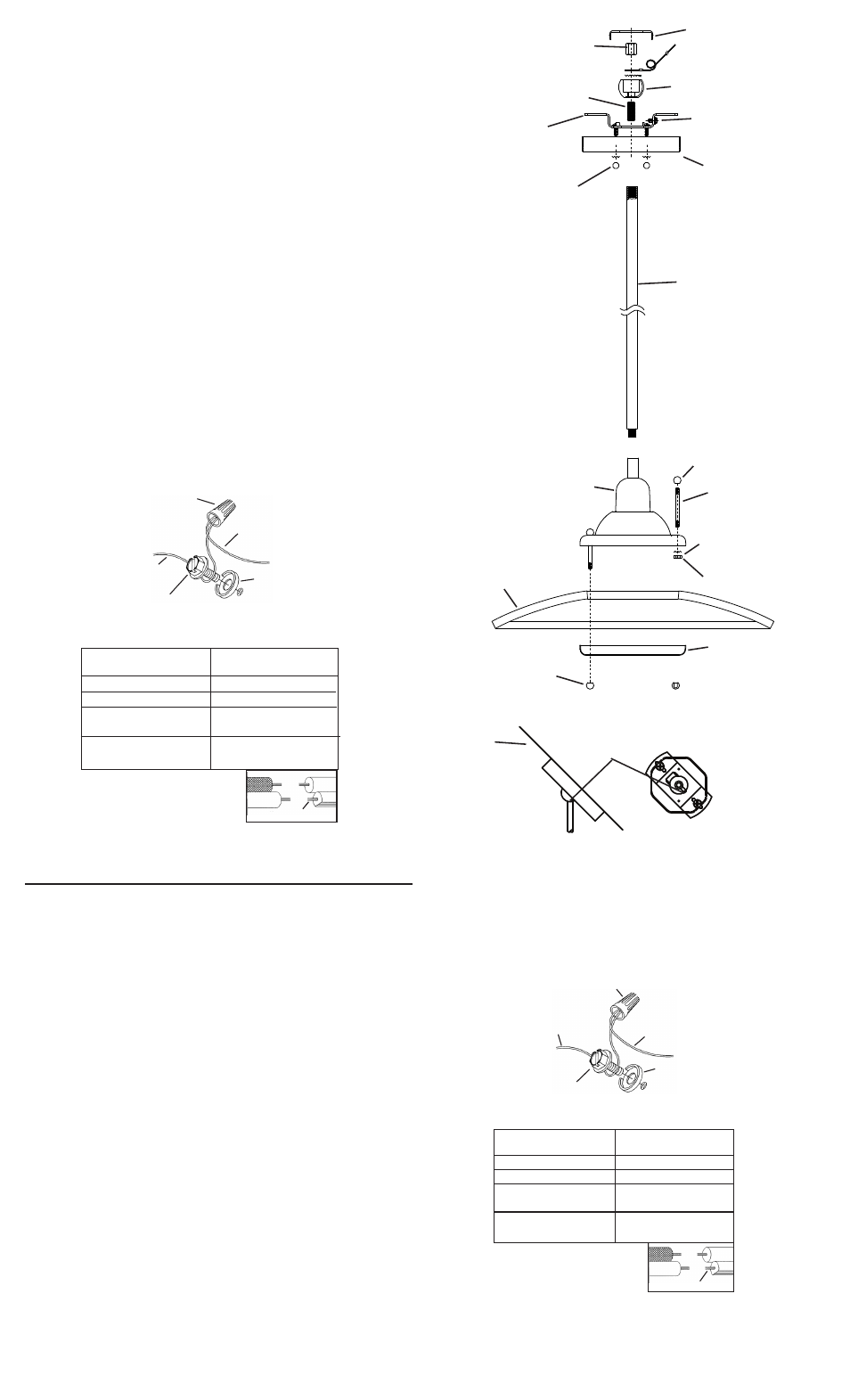
9) Determine the height from ceiling you would like your fixture to hang. Fixture is
provided with (2) 11-1/2” long tubes that can be used or omitted to achieve desired
height.
10) Assemble stem to fixture.
11) Note direction of exposed threaded pipe on illustration. Bottom two pipes will have
exposed thread at top. Top pipe will not have exposed threaded pipe.
12) Install canopy mounting screws, finger tight.
13) Slip canopy then mounting strap over stem(s) assembled to fixture.
14) Thread ball onto pipe until snug against stem Secure ball swivel in place by threading
a hexnut onto threaded pipe inside ball.
NOTE: On fixtures with no ground wire, slip ground jug over threaded pipe inside
ball swivel before threading on hexnut. On fixtures with a ground wire running into
fixture stem or column, attach to supply ground as specified in step No. 14.
15) Lift mounting strap up against ball swivel, aligning slot in ball with lap in strap. Snap
ball retainer into place. Placing one side of ball retainer in place and then snapping
the other in is suggested.
16) Attach assembled fixture/mounting strap to outlet box. Assemble mounting strap to
ceiling with ball slot and tap towards lower portion of slope in ceiling. (REF:
Illustration A)
17) Attach ground wire from outlet box between cupped washer and green ground screw
and thread ground screw into mounting strap. If fixture is provided with ground wire,
connect fixture ground wire to outlet box ground wire with wire connectors (not
provided). Never connect ground wire to black or white power supply wire.
18) Make wire connections (connectors not provided.) Reference chart below for correct
connections and wire accordingly.
19) Carefully slip canopy up stem and secure to ceiling using lockwashers (Canadian
installations only) and ball knobs.
NOTE: Thread locking compound must be applied to all stem threads as noted with
symbol (4) to prevent accidental rotation of fixture during cleaning, relamping, etc.
1) Rosque un capuchón sobre un extremo de una varilla roscada.
2) Deslice el otro extremo de la varilla roscada hacia abajo y a través del orificio
ubicado a lo largo del borde del cuerpo del artefacto.
3) Rosque la arandela de seguridad y luego la tuerca hexagonal sobre la varilla
roscada. Ajuste la tuerca hexagonal para asegurar la varilla en su lugar.
4) Repita los pasos anteriores para las varillas restantes.
5) Deslice el vidrio con cuidado por encima de las varillas roscadas en el cuerpo
del artefacto.
6) Deslice los orificios ubicados en el anillo inferior sobre los extremos de las varillas
roscadas. Coloque el anillo inferior contra la cara interna del vidrio.
7) Rosque los capuchones en los extremos de las varillas roscadas. Ajuste los
capuchones para asegurar el anillo en su lugar. (NO apriete demasiado).
8) APAGUE LA ALIMENTACIÓN ELÉCTRICA.
IMPORTANTE: Antes de comenzar, NUNCA trate de trabajar sin antes desconectar
la corriente hasta que el trabajo se termine.
a) Vaya a la caja principal de fusibles, o interruptor o caja de circuitos de su casa.
Coloque el interruptor de la corriente principal en posición de apagado “OFF”.
b) Desatornille el (los) fusible (s), o coloque el interruptor o interruptores del
breaker en posición de apagado “OFF”, que controla (n) la corriente hacia el
artefacto o habitación donde está trabajando.
c) Coloque el interruptor de pared en posición de apagado “OFF”. Si el artefacto
que se va a reemplazar tiene un interruptor o cadena que se jala, colóquelos en
la posición de apagado “OFF”.
9) Determine la altura de cielorraso a la que le gustaria cogar el artefacto. Se proveen
dos (2) tubos de 11-1/2” de largo con el artefacto, los que se pueden usar u omitir
para alcanzar la altura deseada.
10) Monte el vástago al artefacto .
11) Note la dirección del tubo de rosca expuesta en la ilustración. Los dos tubos
inferiores tendrán roscas expuestas en la parte superior. El tubo superior no tendrá
la rosca expuesta.
12) Instalar los tornillos de montaje delescudete, apretando con los dedos.
13) Deslizer el escudete y luego la abrazadera de montaje sobre el (los) vástago(s)
montados al artefacto.
14) Roscar el pivote en el tubo hasta que esté apretado contra el vástago. Asegurar en
el lugar el pivote a rótula roscando a la tuerca hexagonal en el tubo roscado, adentro
de la rótula.
NOTA: En los artefactos sin alambre de tierra, deslizar la terminal de tierra sobre el
tubo roscado, adentro del pivote a rótula antes de roscar en la tuerca hexagonal. En
los artefactos con un alambre de tierra que va en el vástago o la columna del
artefacto, acoplar a la alimentación de tierra como se especifica en el paso No. 14.
15) Levantar la abrazadera de montaje contra el pivote a rótula, alineando la muesca en
la rótula con la orejeta en la abrazadera. Instalar rápido el retenedo redondo en su
lugar. Se sugiere colocar un lado del retenedor redondo en el lugar y luego
enganchar el otro.
16) Acoplar la abrazadera de montaje/artefacto ensamblados a la caja de salida. Montar
la abrazadera de montaje al cielorraso con la muesca y orejeta hacia la porción más
baja de la inclinación del cielorraso. (Ref: Illustracion A)
17) Acoplar el alambre de tierra de la caja de salida entre la arandela cóncava y el
tornillo de tierra verde, y roscar et tornillo de tierra en la abrazadera de montaje. Si el
artefacto está provisto con un alambre de tierra, conectar el alambre de tierra del
artefacto al alambre de tierra de la caja de salida, con los conectores de alambre (no
se proveen). Nunca se debe conectar el alambre de tierra al alambre de alimentación
negro o blanco.
18) Hacer las conexiones de los alambres (conectores no incluidos.) Ver el cuadro más
abajo para las conexiones correctas y alambrar de acuerdo a esto.
19) Cuidadosamente deslizar el escudete arriba en el vástago y asegurar al cielorraso
usando las arandelas de seguridad (Sólo en instalaciones canadienes) y las perillas
redondas.
NOTA: Debe aplicarse un compuesto para el sellado de roscas en todas las roscas de las
varillas indicadas con el símbolo (4) para evitar la rotación accidental del artefacto
durante su limpieza, cambio de bombillas, etc...
GREEN GROUND
SCREW
WIRE CONNECTOR
(NOT PROVIDED)
OUTLET BOX
GROUND
CUPPED
WASHER
FIXTURE
GROUND
Connect Black or
Red Supply Wire to:
Connect
White Supply Wire to:
Black
White
*Parallel cord (round & smooth)
*Parallel cord (square & ridged)
Clear, Brown, Gold or Black
without tracer
Clear, Brown, Gold or Black
with tracer
Insulated wire (other than green)
with copper conductor
Insulated wire (other than green)
with silver conductor
*Note: When parallel wires (SPT I & SPT II)
are used. The neutral wire is square shaped
or ridged and the other wire will be round in
shape or smooth (see illus.)
Neutral Wire
TORNILLO DE TIERRA
VERDE
CONECTOR DE ALAMBRE
(NO SE PROVEE)
TIERRA DE LA
CAJA DE SALIDA
ARANDELA
CONCAVA
TIERRA
ARTEFACTO
Conectar el alambre de
suministro negro o rojo al
Conectar el alambre de
suministro blanco al
Negro
Blanco
*Cordon paralelo (redondo y liso) *Cordon paralelo (cuadrado y estriado)
Claro, marrón, amarillio o negro
sin hebra identificadora
Claro, marrón, amarillio o negro
con hebra identificadora
Alambre aislado (diferente del verde)
con conductor de cobre
Alambre aislado (diferente del
verde) con conductor de plata
*Nota: Cuando se utiliza alambre paralelo
(SPT I y SPT II). El alambre neutro es de forma
cuadrada o estriada y el otro alambre será de
forma redonda o lisa. (Vea la ilustracíón).
Hilo Neutral
CANOPY
CAPUCHÓN
3
BALL RETAINER
RETENEDOR REDONDO
HEXNUT
TUERCA HEXAGONAL
MOUNTING STRAP
ABRAZADERA
DE MONTAJE
THREADED PIPE
TUBO ROSCADO
GREEN GROUND SCREW
TORNILLO VERDE DE
TIERRA
BALL SWIVEL
PIVOTE A ROTULA
BALL KNOB
PERILLA REDONDA
SLOT AND TAB
MUESCA Y OREJETA
SLOPED CEILING
CIELORRASO
INCLINADO
ILLUSTRATION A
3
CENTER STEM
VÁSTAGO CENTRALE
FINIAL
CAPUCHON
THREADED ROD
VARILLA ROSCADA
HEXNUT
TUERCA HEXAGONAL
FINIAL
CAPUCHON
LOCKWASHER
ARANDELA DE
SEGURIDAD
GLASS
VIDRIO
RING
ANILLO
Date Issued: 1/27/12
IS-2643-US
FIXTURE BODY
CUERPO DEL ARTEFACTO