Kichler 42341 User Manual
Kichler Lighting
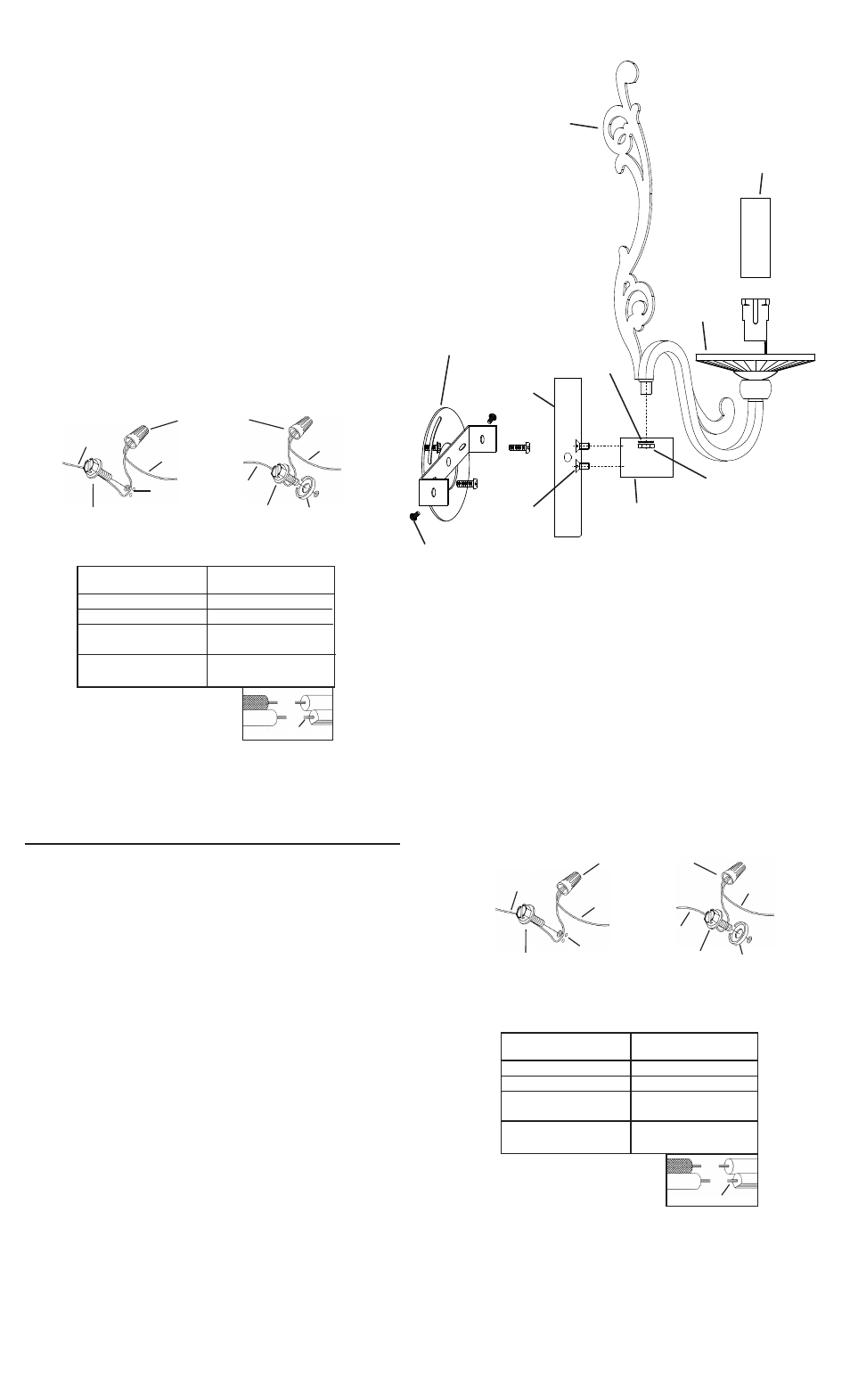
1) Place bar up against front of canopy. Align holes in bar with holes in
canopy.
2) From inside canopy, thread screws through holes in canopy and into
bar. Tighten screws to secure bar to canopy.
3) Insert threaded pipe at end of arm through hole in bar.
4) Slip washer over end of threaded pipe. Screw hexnut onto threaded
pipe. Tighten hexnut to secure arm in place. Repeat for remaining arm.
5) TURN OFF POWER.
IMPORTANT: Before you start, NEVER attempt any work without
shutting off the electricity until the work is done.
a)
Go to the main fuse, or circuit breaker, box in your home. Place
the main power switch in the “OFF” position.
b)
Unscrew the fuse(s), or switch “OFF” the circuit breaker
switch(s), that control the power to the fixture or room that you
are working on.
c)
Place the wall switch in the “OFF” position. If the fixture to be
replaced has a switch or pull chain, place those in the “OFF”
position.
6) Attach mounting strap to outlet box. (Screws not provided).
7) Grounding instructions: (See Illus. A or B).
A)
On fixtures where mounting strap is provided with a hole and
two raised dimples. Wrap ground wire from outlet box around
green ground screw, and thread into hole.
B)
On fixtures where a cupped washer is provided. Attach ground
wire from outlet box under cupped washer and green ground
screw, and thread into mounting strap.
If fixture is provided with ground wire. Connect fixture ground wire
to outlet box ground wire with wire connector. (Not provided.) After
following the above steps. Never connect ground wire to black or
white power supply wires.
8) Make wire connections (connectors not provided.) Reference chart
below for correct connections and wire accordingly.
9) Place canopy over mounting strap, fitting sides of mounting strap inside
canopy. Align holes on sides of canopy with holes on sides of mounting
strap.
10) Thread screws into side of canopy and into mounting strap. Tighten
screws to secure canopy to mounting strap.
11) Lower bobeches down over sockets.
12) Slip candle covers over sockets.
1) Coloque la barra en posición vertical contra la parte frontal del
escudete. Alinee los orificios de la barra con los orificios del escudete.
2) Desde el interior del escudete, rosque los tornillos a través de los
orificios ubicados en el escudete y dentro de la barra. Ajuste los
tornillos para sujetar la barra al escudete.
3) Inserte el tubo roscado en el extremo del brazo a través del orificio
ubicado en la barra.
4) Deslice la arandela por encima del extremo del tubo roscado.
Atornille la tuerca hexagonal sobre el tubo roscado. Ajuste la tuerca
hexagonal para asegurar el brazo en su lugar. Repita con el brazo
restante.
5) APAGUE LA ALIMENTACIÓN ELÉCTRICA.
IMPORTANTE: Antes de comenzar, NUNCA trate de trabajar sin
antes desconectar la corriente hasta que el trabajo se termine.
a)
Vaya a la caja principal de fusibles, o interruptor o caja de
circuitos de su casa. Coloque el interruptor de la corriente
principal en posición de apagado “OFF”.
b)
Desatornille el (los) fusible (s), o coloque el interruptor o
interruptores del breaker en posición de apagado “OFF”, que
controla (n) la corriente hacia el artefacto o habitación donde
está trabajando.
c)
Coloque el interruptor de pared en posición de apagado
“OFF”. Si el artefacto que se va a reemplazar tiene un interruptor
o cadena que se jala, colóquelos en la posición de apagado
“OFF”.
6)
Sujete la banda de montaje a la caja de conexión. (No se
proveen los tornillos.)
7) Instrucciones de conexión a tierra solamente para los Estados
Unidos. (Vea la ilustracion A o B).
A)
En las lámparas que tienen el fleje, de montaje con un agujero
y dos hoyuelos realzados. Enrollar el alambre a tierra de la caja
tomacorriente alrededor del tornillo verde y pasarlo por el
aquiero.
B) En las lámparas con una arandela acopada. Fijar el alambre a
tierra de la caja tomacorriente del ajo de la arandela acoada y
tornillo verde, y paser por el fleje de montaje.
GREEN GROUND
SCREW
CUPPED
WASHER
A
B
OUTLET BOX
GROUND
FIXTURE
GROUND
DIMPLES
WIRE CONNECTOR
(NOT PROVIDED)
OUTLET BOX
GROUND
GREEN GROUND
SCREW
FIXTURE
GROUND
Connect Black or
Red Supply Wire to:
Connect
White Supply Wire to:
Black
White
*Parallel cord (round & smooth)
*Parallel cord (square & ridged)
Clear, Brown, Gold or Black
without tracer
Clear, Brown, Gold or Black
with tracer
Insulated wire (other than green)
with copper conductor
Insulated wire (other than green)
with silver conductor
*Note: When parallel wires (SPT I & SPT II)
are used. The neutral wire is square shaped
or ridged and the other wire will be round in
shape or smooth (see illus.)
Neutral Wire
Date Issued: 7/20/12
IS-42341-US
SCREW
TORNILLO
Si la lámpara viene con alambre a tierra. Conecter el alambre a tierra
de la lámpara al alambre a tierra de la caja tomacorriente con un
conector de alambres. (No incluido) Espués de seguir los pasos
anteriores. Nunca conectar el alambra a tierra a los alambres eléctros
negro o blanco.
8) Haga les conexiones de los alambres (no se proveen los connectores.)
La tabla de referencia de abajo indica las conexiones correctas y los
alambres correspondientes.
9) Coloque el escudete sobre la banda de montaje, encajando los
laterales de la banda de montaje dentro del escudete. Alinee los
orificios ubicados a ambos lados del escudete con los orificios de la
banda de montaje.
10) Rosque los tornillos en el interior del lateral del escudete y dentro de
la banda de montaje. Ajuste los tornillos para sujetar el escudete a la
banda de montaje.
11) Baje los tazones-arandelas (Vidrio de cristal D) sobre los
portalámparas.
12) Deslice los tubos de la vela sobre los portalámparas.
ARANDELA
CONCAVA
A
B
TIERRA DE LA
CAJA DE SALIDA
TORNILLO DE TIERRA,
VERDE
DEPRESIONES
TIERRA
ARTEFACTO
CONECTOR DE ALAMBRE
(NO SE PROVEE)
TIERRA DE LA
CAJA DE SALIDA
TORNILLO DE TIERRA,
VERDE
TIERRA
ARTEFACTO
Conectar el alambre de
suministro negro o rojo al
Conectar el alambre de
suministro blanco al
Negro
Blanco
*Cordon paralelo (redondo y liso)
*Cordon paralelo (cuadrado y estriado)
Claro, marrón, amarillio o negro
sin hebra identificadora
Claro, marrón, amarillio o negro
con hebra identificadora
Alambre aislado (diferente del verde)
con conductor de cobre
Alambre aislado (diferente del
verde) con conductor de plata
*Nota: Cuando se utiliza alambre paralelo
(SPT I y SPT II). El alambre neutro es de forma
cuadrada o estriada y el otro alambre será de
forma redonda o lisa. (Vea la ilustracíón).
Hilo Neutral
ARM
BRAZO
CANDLE COVER
TUBO DE LA VELA
BOBECHE
TAZONE-
ARANDELA
CANOPY
ESCUDETE
SCREW
TORNILLO
BAR
BARRA
HEXNUT
TUERCA HEXAGONAL
WASHER
ARANDELA
MOUNTING STRAP
BANDA DE MONTAJE