Connection & wiring diagrams, Pd662 loop-powered meter instruction manual, Figure 1. pd662 mounting board rear view – Precision Digital PD662 User Manual
Page 11: S+ s - b- s+ s - b
PD662 Loop-Powered Meter
Instruction Manual
11
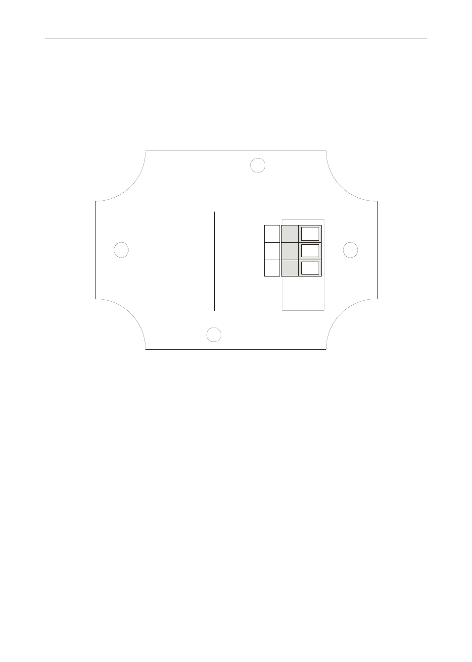
Refer to Figure 1 for terminal positions on the rear of the mounting board
inside the meter enclosure.
Meters with the heater option will also have a two terminal removable
connector on the rear of the assembly. See Figure 4 for wiring details.
P+
24 VDC power positive terminal connection
P-
24 VDC power negative terminal connection
W
IR
IN
G
IN
S
T
RU
CTI
O
NS
C
o
nn
ec
t s
ig
n
al
p
os
iti
ve
to
te
rm
in
al
S
+.
C
o
nn
ec
t s
ig
n
al
n
eg
a
tiv
e to
te
rm
in
al
S
-.
If ba
ck
lig
ht
in
st
al
le
d,
c
on
nec
t
si
g
na
l n
eg
ati
ve
to
t
er
m
in
a
l B
-, n
o
t S
-.
S+
S
-
B-
S+
S
-
B-
Figure 1. PD662 Mounting Board Rear View
Connection & Wiring Diagrams
Signal input connections are made to a three-terminal connector labeled
S+|S-|X for models without a backlight and S+|S-|B- for models with a
backlight. The 4-20 mA input with no backlight has a maximum voltage
drop of 1.7 V and is wired as shown in Figure 2. The loop-powered
backlight configuration requires a total maximum voltage drop of 3.7 V.
The backlight is recommended for dim lighting conditions and is enabled
when wired as shown in Figure 3.