Leds display, Relay mode / bus mode jumper, Optional swivel installation (not supplied) – RISCO Group Wireless WatchOUT PIR 312PR User Manual
Page 10: Wall mounting
10
WatchOUT PIR Installation Manual
LEDs Display
LED
State
Description
GREEN
Steady
Indicates upper PIR detection
YELLOW
Steady
Indicates moving PIR detection
RED
Steady
Indicates ALARM (Simultaneous 2 PIR channels)
Flashing
Indicates malfunctioned communication with ProSYS (BUS mode
only)
All LEDs
Flashing
(One after
another)
Unit initialization on power up
Notes
:
1. DIP-Switch 1 should be in ON position to enable LED indications.
2. Only one LED is active at any one time. For example, in the case of both PIR channels detection, either the
steady yellow LED or the steady green LED is displayed (the first to detect), followed by the alarm red LED.
Relay Mode / Bus Mode Jumper
J-BUS jumper (located on the PCB between the red and
green LEDs) is used to define the detector’s mode of
operation as follows:
Relay
Mode
BUS Mode
O
N
O
N
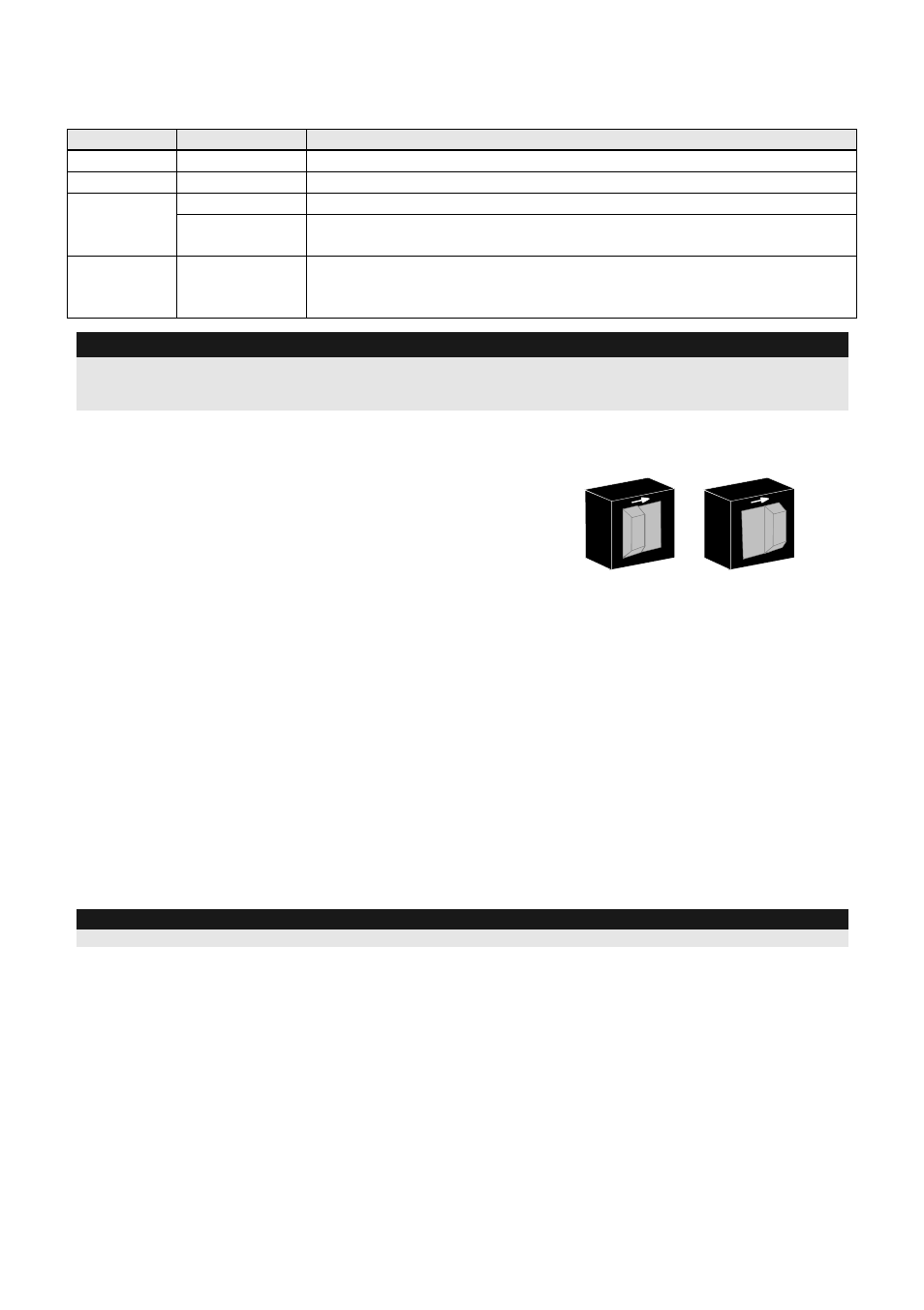
Optional Swivel Installation (Not Supplied)
Please follow the instructions below for mounting the detector with the Standard Swivel:
1.
Open WatchOUT front cover (Unlock C1, Figure 1).
2.
Release internal base (Unlock I1, Figure 2).
3.
Open knockouts on external base (Figure 8, Detail B)
W1: Wires knockout
S1,S2: Knockouts for securing external base to Standard Swivel
S3: External base locking screw knockout
4.
On the swivel accessory remove the required swivel cable wiring knockout S2, S7 or S9
(Figure 8, Detail A).
5.
Remove back tamper from the internal base
(see “Changing Back Tamper Position"
paragraph) and connect it to S5 (Figure 8, Detail A) on the Standard Swivel.
6.
Select the mounting installation as follows:
Note:
Ensure that you see the engraved UP mark on the upper front face of the swivel.
Wall Mounting
a.
Insert external cable wiring through knockouts S2, S7 or S9 and extract them (including the
tamper wires) through the Swivel Wires Passage (Figure 8, Detail B).
b.
Secure swivel to the wall through holes S1, S3, S6 and S8.