Changing back tamper position, Terminal wiring, En g li s h changing back tamper position – RISCO Group Wireless WatchOUT PIR 312PR User Manual
Page 7
WatchOUT PIR Installation Manual
7
E
n
g
li
s
h
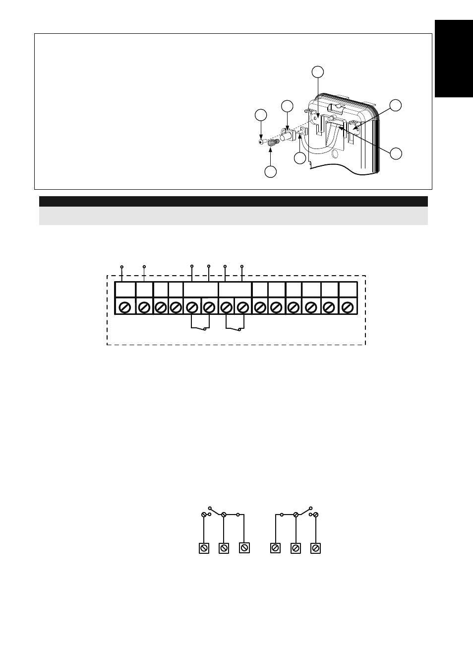
Changing Back Tamper position
The back tamper is by default secured on the
right side of the internal base (Rear view). If
you wish to move it to the left side (rear view),
do the following (Figure 5):
1. Remove tamper screw 1 in order to
release the tamper from position 7.
2. Ensure tamper spring 2 rests over tamper
wire base 4.
3. Ensure plastic tamper bracket 3 rests over
both 2 and 4.
4. Secure tamper screw 1 into 3 over
position 6.
Figure 5
Left Side
Tamper
Right
Side
Tamper
3
6
1
2
4
7
5
Notes:
a.
Verify that you hear a "Click" when attaching the tamper spring to the wall.
b.
For pole installation, the tamper can be moved to the bottom right-hand side of the internal base.
Terminal Wiring
12VDC
N.C
N.C
+
-
LED
ENABL
ALARM
FREE
N.O COM
GRN
YEL
TAMPER
FREE
N.C
WatchOUT PIR - PCB
+,-
12 VDC
YELLOW
N/A (Used only for BUS mode installation)
GREEN
N/A (Used only for BUS mode installation)
ALARM
N.C relay, 24VDC , 0.1A
TAMPER
N.C relay, 24VDC , 0.1A
FREE
A free terminal that can be used to connect wires and EOL resistors
LED
ENABLE
Used to remotely control the LEDs when DIP1 is set to ON (used in high security
environments).
LED Enable
: input is +12V OR no terminal connection.
LED Disable
: Connect the input to 0V.
N.O
Programmable auxiliary relay terminals. This relay is used to activate auxiliary
units such as cameras or lighting when an alarm is triggered.
The operation of the auxiliary relay depends on the settings of DIP switches 4-7.
NORMAL
N.O
COM
N.C
ALARM
N.C
COM
N.O
COM
N.C
WatchOut 312PR - PCB