Bus mode installation, Introduction, Terminal wiring – RISCO Group Wireless WatchOUT PIR 312PR User Manual
Page 14: Cover and back tamper, Cover tamper only, Cover tamper to zone input, Dip switch settings, Bus mode installation introduction, 14 watchout pir installation manual, Dip switch number description 1 - 5
14
WatchOUT PIR Installation Manual
BUS Mode Installation
Introduction
The information in this section relates to WatchOUT 312PR installation in BUS Mode only. Up to
32 bus detectors can be installed on the ProSYS RS485 bus, saving cabling time and enabling
remote control and diagnostics.
Terminal Wiring
+,-
Used for the connection of 12VDC power supply. Connect the (+) terminal to
the AUX RED and the (
–) terminal to the COM BLK of the ProSYS terminals
YELLOW
Used for data communication with the ProSYS. Connect to the terminal to the
BUS YEL
of the ProSYS
GREEN
Used for data communication with the ProSYS
.
Connect to the terminal to the
BUS GRN
of the ProSYS
TAMPER
Used for the wiring for tamper detection, see below
LED
ENABLE
Used for the wiring for tamper detection, see below
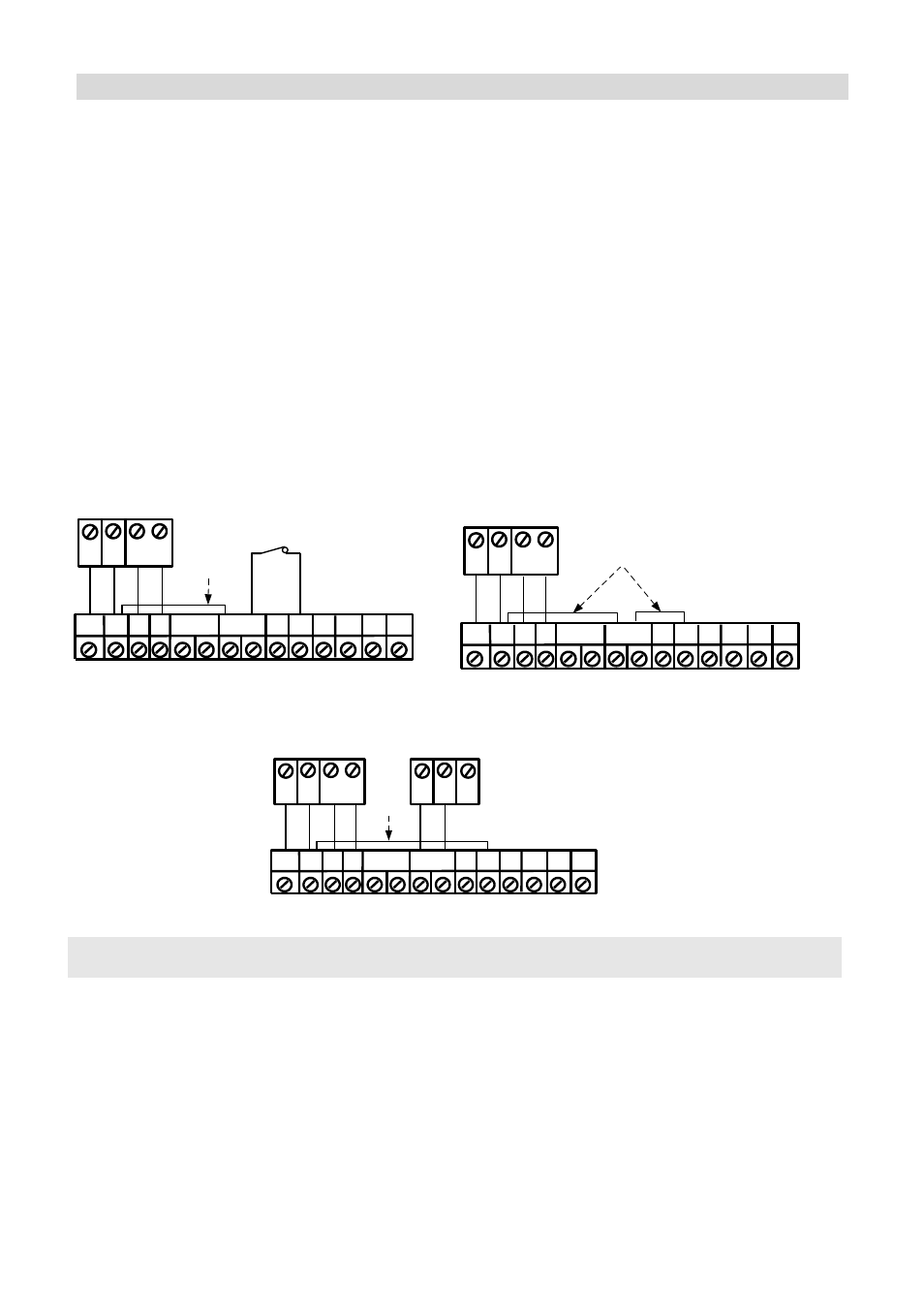
Cover and Back Tamper
+
-
LED
ENABL
ALARM
FREE
N.O COM
GRN
YEL
TAMPER
FREE
N.C
COM
BLK
BUS
GRN
YEL
BUS Mode:
Cover + Back tamper wiring
BACK
TAMPER (N.C)
ProSYS
Short
AUX
RED
Cover Tamper Only
+
-
LED
ENABL
ALARM
FREE
N.O COM
GRN
YEL
TAMPER
FREE
N.C
COM
BLK
BUS
GRN
YEL
BUS Mode:
Cover Tamper Wiring
ProSYS
Short
AUX
RED
Cover Tamper to Zone Input
COM
BLK
BUS
GRN
YEL
BUS Mode:
Cover Tamper to Zone Input
ProSYS
BUS
Short
COM
Z1
Z2
Zone
Input
AUX
RED
+
-
LED
ENABL
ALARM
FREE
N.O COM
GRN
YEL
TAMPER
FREE
N.C
DIP Switch Settings
DIP Switch
Number
Description
1 - 5
Used to set the detector ID number. (See Table 1) Set the ID number in the
same way as for any other ProSYS accessory (Refer to the ProSYS installation
instruction manual)
6 - 8
Not used