Resistance and continuity measurement – Amprobe ACD-51HP Power-Quality-Clamp-Ons User Manual
Page 18
ACD-51HP - ACD-56HPQ
4.3.4. Resistance and continuity measurement
WARNING
Before attempting any resistance measurement remove the power from the
circuit under test and discharge all the capacitors, if present.
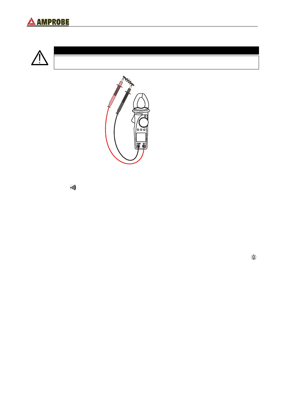
Fig. 8: resistance and continuity measurements
1. Select the “
Ω
” position.
2. Insert the red plug into V/
Ω jack and the black plug into COM one. For an easy
measurement use the rubber test lead holster inserting in it one test lead (see Fig. 3).
3. Connect the test leads to the circuit under test (see Fig. 8). The measured resistance
value is displayed.
4. An audible beep sounds when the measured value is lower than 40
Ω.
5. The symbol "
O.L
" means that the measured voltage is higher than the full scale of the
instrument.
6. If the display is difficult to read, press D-H key to hold the measured value. To disable
this function press the D-H key again.
7. If the measurement is being performed in a dark environment, press and hold the
key for 1 second to activate the backlight. It automatically turns OFF after 5 seconds.
By pressing and holding the MAX/MIN/PK key at least for 1 second, the instrument
activates the maximum (MAX), minimum (MIN) and average (AVG) measurements. All
these values are continually updated even if only one of them is shown. With a simple
MAX/MIN/PK key press the values are cyclically displayed. To escape this function press
and hold pressed MAX/MIN/PK key at least for 1 second or turn the selector to any
position.
EN - 14