Detection of phase coincidence, Warning – Amprobe ACD-51HP Power-Quality-Clamp-Ons User Manual
Page 28
ACD-51HP - ACD-56HPQ
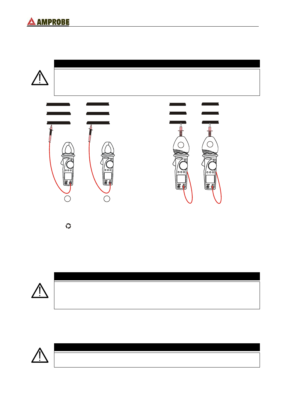
4.3.10.1. Detection of phase coincidence
The purpose of this measurement is to verify the correct phase between 2 conductors
before executing a parallel connection.
WARNING
The maximum Voltage input is 600V. Do not attempt to take any voltage
measurements exceeding the limits indicated in this manual. Exceeding the
limits could cause electrical shock or damage to the instrument.
L3
L2
L1
L3
L2
L1
1
2
L3
L2
L1
L3
L2
L1
1
2
Fig. 16: phase detection
Fig. 17: phase detection with rubber cup
1. Select the “
” position.
2. Insert the red plug into V/
Ω jack.
3. The symbol “
1
PH
” is shown on the secondary display, the instrument is ready to
perform the first measurement.
4. Connect the red terminal to the L1 phase conductor (see Fig. 16, 1
st
measurement). If
necessary use the rubber cup to insert red test lead (see Fig. 17, 1
st
measurement).
WARNING
During this measurement:
• The instrument must always be held in the operator’s hand.
• The test lead cable must not be in contact with or near to any voltage
source that, due to instrument sensitivity, can abort the measurement.
5. When an input voltage greater than 80V is detected the buzzer sounds and the
symbols “
PH
” is shown on the main display. Don’t press any key and keep the test
lead connected to L1 phase cable.
WARNING
If the input voltage value is less to 80V the instrument doesn’t show the
“
PH
” symbol and it’s not possible to execute the phase rotation detection.
EN - 24