Amprobe PRM-6 User Manual
Page 10
6
DISPLAY
L1 MISSING
L2 MISSING
L3 MISSING
L1
A
L2
B
L3
C
ONE INPUT
CONNECTED
TO N OR PE
OFF
ON
CORRECT
FALSE
R
L
L R
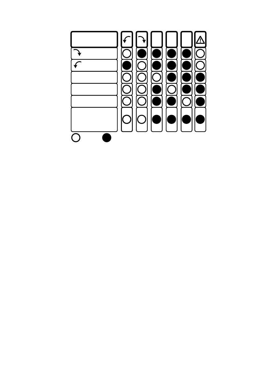
Figure 1: Phase indication table
(also printed on the back of the PRM-6)
Non-Contact Rotary Field Indication
For non-contact rotary field indication:
1. Disconnect all test leads from the PRM-6 for safety reason.
2. Position the PRM-6 on the motor so it is parallel to the length of the
motor shaft. The sensor of the tester should be in the center of the
motor windings. The tester should be as close as possible to the motor.
See Figure 2.
3. Press and hold the ON button. The LC display shows “ON,” indicating the
PRM-6 is ready for testing.
4. Either the clockwise or counter-clockwise rotary indicator will illuminate,
showing the type of rotary field direction present.
If the LC display don’t show the “ON” symbol, while pressing the ON button,
the battery does not have a charge and needs to be replaced.
W
The Indicator will not operate with motor controlled by frequency
converters. The bottom of the PRM-6 should be oriented towards the drive
shaft. See the Orientation Symbol on the PRM-6.
If the motor was disconnected from electricity for a long time (typically one
year), the residual field / magnetization may be too weak for the tester to
measure the rotation.