Prm-6 motor and phase rotation tester, Probe tip cap (black, red, yellow), Test probe (black, red, yellow) – Amprobe PRM-6 User Manual
Page 6: Alligator clips (black, red, yellow)
Advertising
2
1
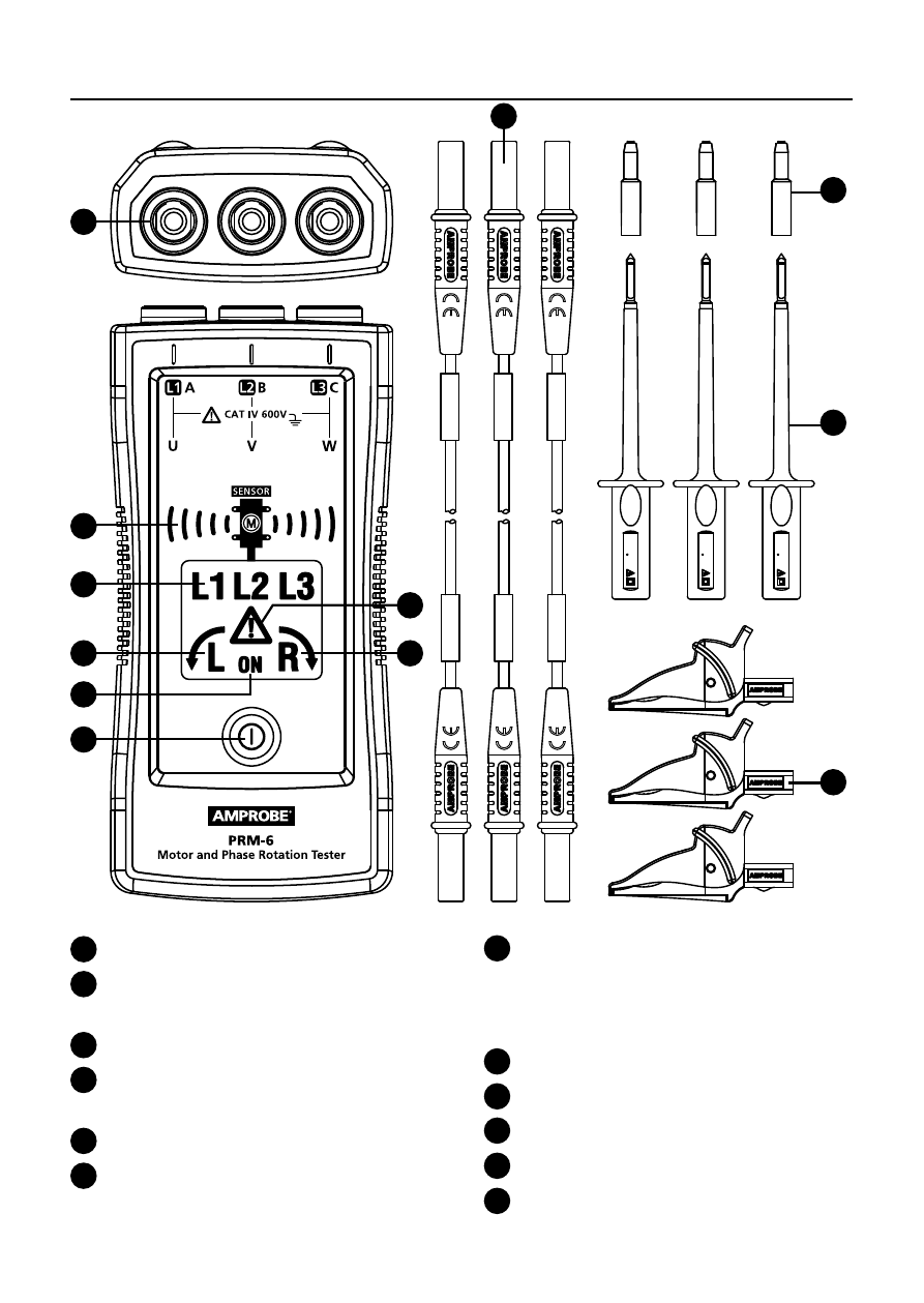
Input terminals for L1 (A), L2 (B), L3 (C)
2
Non-contact motor orientation
symbol and sensor indicator
3
Symbol for L1, L2, L3 indicators
4
Symbol for counter-clockwise
rotation
5
Symbol for clockwise rotation
6
“Warning symbol” for false input
voltage
PRM-6 Motor and Phase Rotation Tester
7
ON symbol for Non-Contact
Rotary Field Indication
and Determine the Motor
Connection
8
ON button / Backlight
9
Test leads (black, red, yellow)
10
Probe tip cap (black, red, yellow)
11
Test probe (black, red, yellow)
12
Alligator clips (black, red, yellow)
a
6A
x
m
C
A
T II
1000
V
CAT IV 600V
a
6A
x
m
C
A
T II
1000
V
CAT IV 600V
a
6A
x
m
C
A
T II
1000
V
CAT IV 600V
615
57
-7
L1
/A
615
57
-7
L2
/B
615
57
-7
L3
/C
4
5
8
7
1
3
2
6
10
11
12
9
Advertising