Amprobe PRM-6 User Manual
Page 11
7
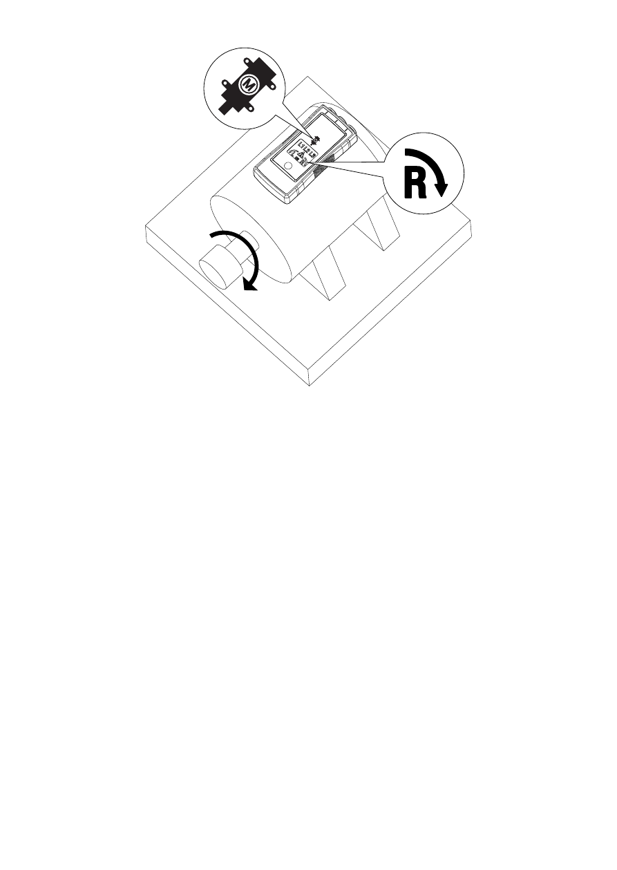
Figure 2: Motor Rotation
Determine the Motor Connection
1. Connect one end of test leads to the tester’s corresponding terminals L1,
L2, and L3.
2. Connect the alligator clips or the test probes to the other end of the test
leads.
3. Connect the alligator clips or test probes to the motor connections, L1 to
U, L2 to V, L3 to W.
4. Press the ON button. The LC display shows “ON,” indicating the PRM-6 is
ready for testing.
5. Turn the motor shaft towards the right.
6. Either the clockwise or counter-clockwise rotary indicator will illuminate,
showing the rotary field direction.
If the LC display don’t show the “ON” symbol, while pressing the ON button,
the battery does not have a charge and needs to be replaced.
Note: If you get a another indication of the rotary field direction as expected
then swap two connection from step 3 and repeat testing. Use the new order
of U (L1), V (L2) and W (L3) for further purpose